One of the big problems with modeling the CR&NW is the sheer amount (and variety) of bridges the line had. My layout gets some of the most iconic of the large ones – Miles Glacier, Chitina, Kuskulana, Gilahina, and McCarthy. Some are significantly shortened, such as Miles Glacier at only 40% because I don’t have room for a bridge 10 feet long, some are done at maybe 60-70% full size (McCarthy, Chitina, Gilahina and its “modern” replacement), and Kuskulana is done at nearly 100% full scale.
They’re all scratchbuilding or serious kitbashing projects, because for obvious reasons none of them exist as kits (or even anything close). That sounds like a lot of fun, but it also means the results will be one-off hand built models that will take weeks, if not months, to complete if done to the accuracy I want. In the meantime, I’m going to be working around them doing scenery, painting, etc. that’s likely to accidentally damage a real model.
The upper deck main line has been inoperable for nearly a year now since I removed the temporary plywood bridges at Kuskulana and Gilahina, as they were in the way of starting latticework to support the scenery hard shell. Those gaps in the mainline actually have been a huge mental block. The “not being able to run a train” factor combined with the overwhelming nature of all these bridges to model. About two weeks ago, I decided it was time to build something between plywood and the final models – some temporary bridges. Close enough to the real thing to be plausible, but cheaply and quickly constructed using 3D printing.
Temporary Bridges
3D printing has come a long way since I started on this layout a decade ago. (Yes, it’s been that long. Yes, I’m as disappointed in myself as anybody for the lack of progress.) The final structures for a lot of these will probably be created on a SLA (resin) printer, which can now turn out absurd levels of detail with good strength. But those will need very intricate CAD models to produce.
For now, what I needed was stand-ins for the final structures. Stuff that could hold up the track, was dimensionally correct and had the right general appearance and “flavor” so that I could see how it would look in the final scene. However, the goal was stuff that could be printed quickly and cheaply on just a good old standard FDM (filament) printer, so that I could crank off a number of iterations to test appearance and fit on the layout.
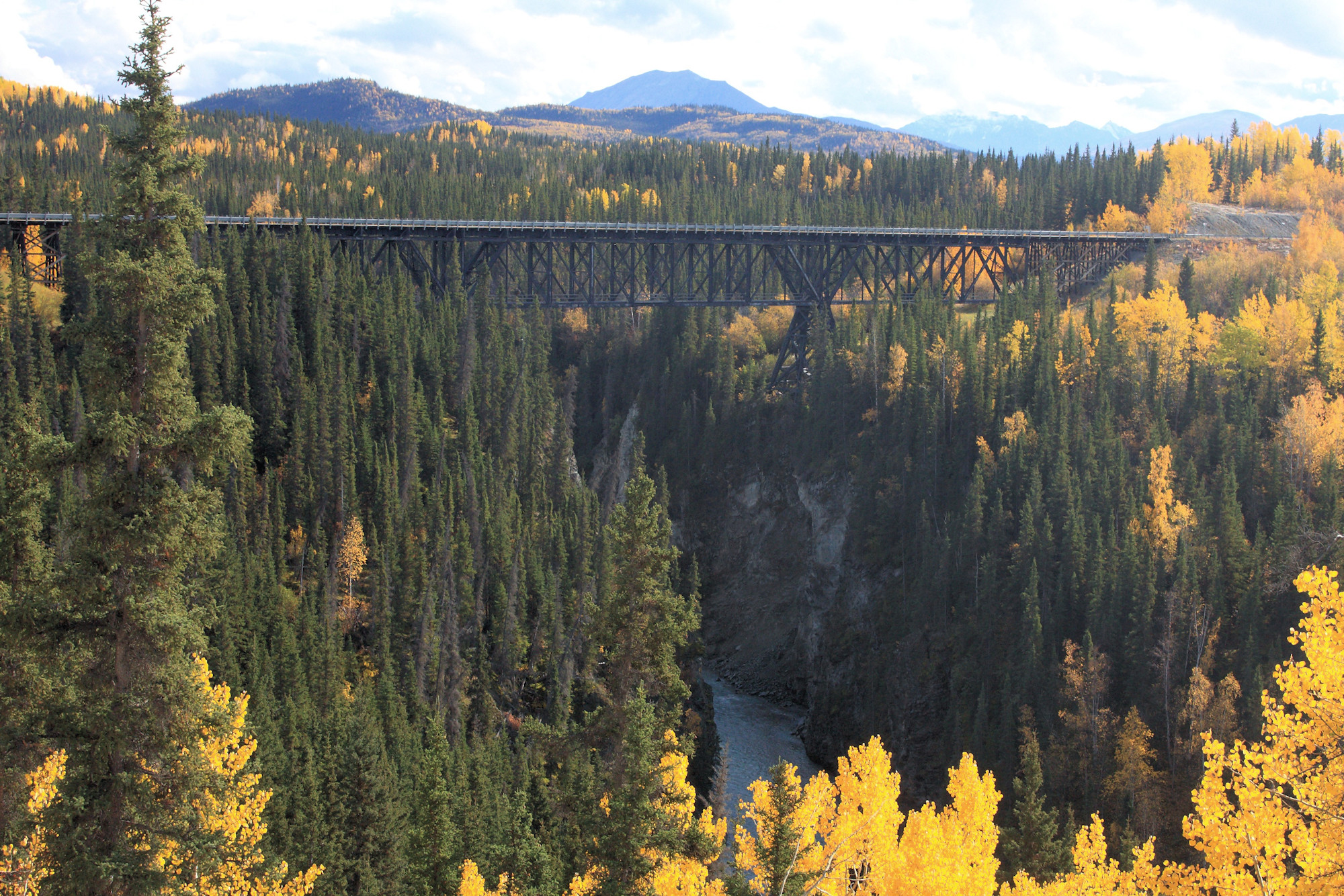
Gilahina
I started with Gilahina, not because I’m modeling the old trestle – for which I have reasonably good detail photos and measurements from my 2015 trip – but rather because my “modern day” CRNW would have bypassed it years ago anyway.
Large wooden trestles like that would have been unlikely to remain in service longer than maybe the late 1950s, given the challenging environment it lives in. Massive temperature swings, moisture, permafrost heaving, etc. all take their toll. In addition, the relatively tight curvature would require a fairly significant slow order for more modern, heavier trains. Therefore, I’d long ago made the decision to model it much as it exists today – the trestle will be a derelict monument to a past era, tucked in behind the modern bridge.
I considered a number of bridge designs – steel trestles, larger truss spans and fewer piers – but settled on a nine-span deck girder bridge setting on cast concrete piers, using a straightened alignment from the original curved crossing.
However, in my fictional modern day CRNW, large trestles like that would not have survived past the first generation diesel era. Somewhere in the 1950s or 1960s it would have likely been changed out for a modern structure – in my world, a long deck girder bridge. So, the final space is designed to be occupied by eight Micro Engineering 80-ft ballasted deck girder bridges sitting on cast concrete piers.
(Trivia: The model is loosely inspired by the B&O Pleasant Valley bridge south of Grafton, WV. I was out railfanning the A&O one day, looked over and thought, “Yeah, that’s roughly the look I want.” Turns out it was built in the 1930s as part of a line relocation project, so it’s a little early, but I went with it.)
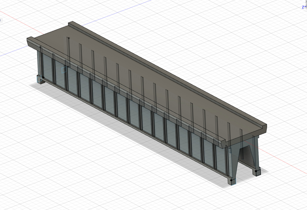
I sat down with Fusion and drew up a dimensionally-equivalent deck girder bridge to the Micro Engineering models, but with significantly less detail. Basically, optimized to be a strong, cheap stand-in until the layout was ready for the real thing.
For those who want the bridge, I’ve put the STLs over on Thingiverse in a number of different variants. There’s the whole bridge as a single unit if you don’t want to print it in two different colors, and then there’s the deck, the ribbed girders, and a smooth-sided variant of the girders that would more accurately model a modern bridge built out of weathering steel or such. Here’s the link.


 workbench")


Kennicott River (McCarthy)
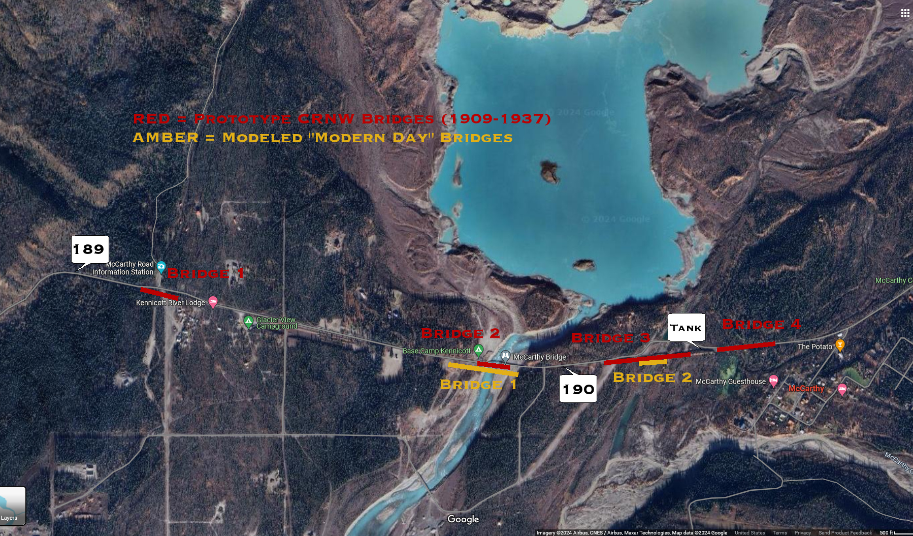
With the Kennicott River crossing, we have much the same situation as at Gilahina. Kennicott on the prototype was at least four long, low timber trestles. From west to east geographically:
- Small trestle at MP ~189.1 over what the 1909 survey maps list as “Kennicott River Dry Channels”
- Small trestle at MP ~189.9 or so over what’s listed as “glacier stream”
- The main trestle starting at maybe 190.2 or so and running for maybe 0.2 miles over the “Main Channel Kennicott River” The railroad’s water tank was constructed on a small island between this and the fourth trestle.
- A fourth small trestle over another small overflow channel just before the curve past the McCarthy freight house and depot.
When the railroad was originally built, the foot of the glacial ice was indicated on the map just north of the grade, literally within a couple hundred feet. Today the glacier has retreated up the valley, perhaps a mile or so from the bridge site. This movement has changed the hydrological patterns and caused the Kennicott River’s channel to shift.
Today, that westernmost trestle is completely dry, the second small trestle is now the main channel of the Kennicott, the former main channel trestle is an overflow channel that only sees a small amount of water except during floods, and the easternmost trestle channel is just swampy.
So, a modern day CRNW would need two bridges – one over the new main channel and one over the eastern overflow channel (former main channel). This is very similar to where the foot bridges are constructed.
Here’s a rough overlay onto Google Maps showing where the various bridges were located.
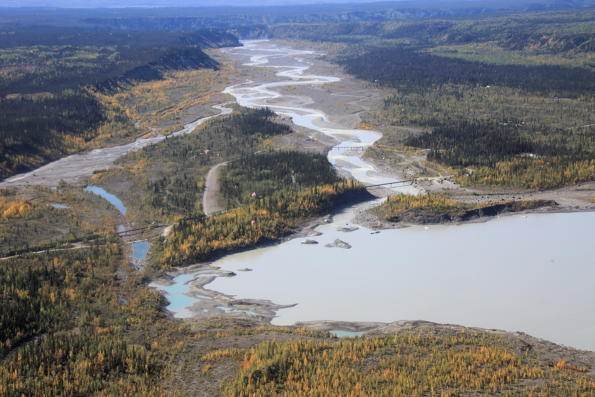
And here’s an aerial look at the two channels back in 2015. The main (eastern) channel is on the right, and the old main channel is on the left. You can also see the privately-built road bridge for local residents over the main channel somewhat further downstream.
Going with a trestle is probably a bad idea in general, however. The Kennicott and Root Glaciers which combine to start the Kennicott River have at least six lakes dammed up underneath them. One of them – Hidden Creek Lake – is sizable, and lets go nearly every year in the late summer or early fall as a massive flood event known as a jökulhlaup, or glacial outburst flood. This event, and outbursts from the other subglacial lakes, routinely destroyed the main channel trestle. Again a modern railroad can’t be rebuilding its bridges every summer when the glacier throws a fit. A new, better bridge is in order.
Trestles have lots of piles set in to the river with relatively short spans, so they’re prone to taking damage from flooding with all those supports, and they’re prone to blockage from debris, which only adds to the load and bridge damage. Here we’ve got huge surges of water carrying all manner of debris – rocks, ice, any trees scoured off the banks, etc. Any sort of trestle really needed to go in favor of something much more stout. Because the approaches on each side are built over alluvial terraces in the Kennicott River bottoms, there’s not a lot of elevation change. Any bridge would want to maximize the amount of space underneath for all that debris to pass.
So, for this case, I decided on plate girder spans set on cast concrete piers. That maximizes the space under the span without requiring raising the railroad across the entire flood plain. Well-engineered concrete piers should be up to the task of withstanding the deluge of water, ice, mud, and rocks as long as leading face is reinforced and at a pretty good angle. Plus, we’re going to need end abutments with some serious wing walls, because as we’ve seen, these flooding events like to cut into the banks and move the channel around.
Unlike Gilahina, here I went with the real bridge models. There’s not nearly as much scenery to be done in and around the Kennicott River crossing. It’s a narrow shelf area and there’s a removable backdrop panel behind it to access one of the basement windows, so I’m not going to be doing much except low ground scenery. Also, the Atlas plate girder bridges are not hard to find, unlike the Micro Engineering deck girder kits. I just close-joined three spans for the main channel, attached some Micro Engineering bridge shoes to them and drew up some piers. The piers and abutments are roughly based around a design done for the Chicago & Alton in the 1920s that I found drawings for online.


 looking towards McCarthy.")

Kuskulana
I saved the biggest of the temporary bridges I’ve built so far for last. Kuskulana is the bridge that captured my imagination as a kid back in 1989 and lead to a life-long fascination with this railroad. As such, I knew when I built the layout that I needed to capture it at nearly full size so as to keep that sense of awe by those who see it for the first (or tenth) time. The approach trestles are shortened up, but the bridge itself – and the canyon beneath – are done to scale.
Unfortunately, it’s also a pain in the ass to model. I’ve yet to find any drawings of the bridge, and all I had to work with are a bunch of hastily scribbled measurements I made in the pouring rain (and hail) back in 2015. Fortunately between that and measuring dozens of photos – both mine and others – I’ve come up with a set of measurements that produces a reasonable model. The purpose of building this test bridge was very much to test the dimensions and see if what I’d come up with fit correctly into the layout. Well, in addition to getting trains back across the deep chasm.
Spans 1 and 3 of Kuskulana are identical as far as I can tell. They’re both 150ft long and look to be twins. Likewise, they’re nearly symmetric in half, meaning if you split them right down the center vertical post, the two halves of each span appear to be mirror images of each other. Span 2, on the other hand, is 225ft long. The outer 150ft appear to be approximately the same as the spans 1 & 3, except for some heavier upper and lower truss elements. The middle 75 feet (3 panels) is completely different, with a big pin connection between the bottom truss chords from each and.
Working up a CAD model in Fusion, I stuck to my theory of “temporary bridge.” All the great lattice girders were simplified to boxes of basically the right dimensions. Things that were too small to print reliably were upsized. The goal was to get this built in a day or two to verify fit and appearance, and get the mainline reconnected. So while the basic dimensions are correct, most of the small detail is thrown out in the interest of simplicity and durability. When I go back and do the final model, I can have confidence that I have the basic dimensions worked out and it’s just a matter of rebuilding it with all the little details.
I also quickly realized there was no way to print any whole span as one piece. They were both too internally complex and required too much support material, and they were just too darn big for my print bed. So using the symmetry above, I printed things in 75 ft segments, and cut it vertically between the top truss chord and the posts. Once off the printer, the top first got glued to the main truss segment. Then I used these “span halves” connected end-to-end with wooden dowels inserted to make spans 1 & 3.
Span 2, being different, had a special middle truss segment made that fit between the two ends. (I did make a mistake, however. One of the inner sets of posts is missing its cross-bracing. Oops.)
The large pedestals, some ~41 feet from the top of the bearings mounted to the concrete footers to the bottom of the shoes attached to the trusses, appear to be the same from each side of the canyon. The exact positions of each set of cross-members is a guess based on photos. (Note: the land side and canyon side of each is different.) These I built to split vertically and printed them with the large side towards the print bed. Once printed, the two halves got glued together. I then printed temporary foundations with footer bearings attached, and glued the pedestals on.
Once all the pieces were made, I glued span 2 to both pedestals on the workbench to assure everything was square. With that done, I then test fit the whole thing into the canyon and marked where the outer concrete bridge piers needed to be located for the land-side ends of spans 1 & 3. With those installed, I lined everything up with a laser, shimmed the two pedestal bases to get everything level, and CA’d the whole thing together.
While that glue was setting, I took four segments of Central Valley bridge ties and two pieces of fresh Micro Engineering code 55 flex track. I stripped the ties from about half of each piece and joined them. Once again on the bench, I cut the CV bridge ties so that they would be solid segments over the bridge gaps. Then I put some CA on the bottom of the rails, and made one long continuous bridge deck with enough flex track left at each end to bridge the trestle approaches and connect to the mainline.
Once it had time to set, I did one last alignment check and glued the bridge deck on, making the bridge one big solid piece. A little hot glue along the edges to hold the pedestal bases in the right spots kept the thing aligned. After that, it was a matter of connecting the rails, cleaning the track, and firing up a test train to run across it.


.")


And with that, I leave you with a video I shot of the first run. The bridge isn’t a final detailed model, but I’m still giddy every time I walk around the corner and see it there. Finally I have one of those signature elements that’s starting to make this feel like the CRNW and not just some layout.