Category Archives: Planning

Posts related to the overall planning of the layout

Powering the Layout

In addition to track power, which is something most of us have provided by our DC throttles or DCC systems, most of us have a ton of accessories. That can be as basic as things like switch machines or a hodge-podge of building lights, animated features, signals, sound modules, etc. Nearly every single one of those is going to have its own requirements in terms of voltages, currents, etc. Most layouts I’ve ever been on solve this by a maze of power strips, wall warts, battery packs, and old DC power packs repurposed once the owner converted to DCC. It’s a mess.

As an electrical engineer, some things about how people build layouts bug me far more than they should. Messy, disorganized power systems are definitely at the top of the list. I thought I’d give you a look at how power is distributed around my layout to run everything that’s not the track.

Continue reading

Hand-laid Track, Here We Come!

Before I left for home to be with family for Christmas, I had another point rail on an Atlas Code 55 turnout break.  The stamping process appears to leave a weak spot right where the point rail connects to the throwbar, and some of them tend to break.  This is the third of this type of failure I’ve seen, and this makes me suspicious that it may be a common problem.  Combined with my frustration at the complete lack of Atlas C55 availability, I’ve decided it’s time to make some changes.

A few hours before leaving for Iowa, I bit the bullet and ordered a #7 Fast Tracks turnout building kit and associated hardware.  I’ve heard nothing but good things about these guys and decided it was time to give it a shot.  It’s a little pricey to get started, but once I have the jigs and tools, I’ll never be beholden to any company not having track piece X in stock again.  Plus, I’ll be switching to Micro Engineering C55 flex track.  Visually it’s on par, if not a touch better, than the Atlas flex track I already have and the rail will then be identical to my new turnouts.  I don’t like the more rigid design, but it’s made in the good ol’ USA and – surprise – you can actually get it.

The kit should be waiting in the mail when I get home, but I’m still missing a few things like the files that won’t show up until tomorrow.  Hopefully by the end of the week I can actually try out building a turnout and I’ll post again with my thoughts and results.

Proto-Freelancing: The Third Copper Crossing

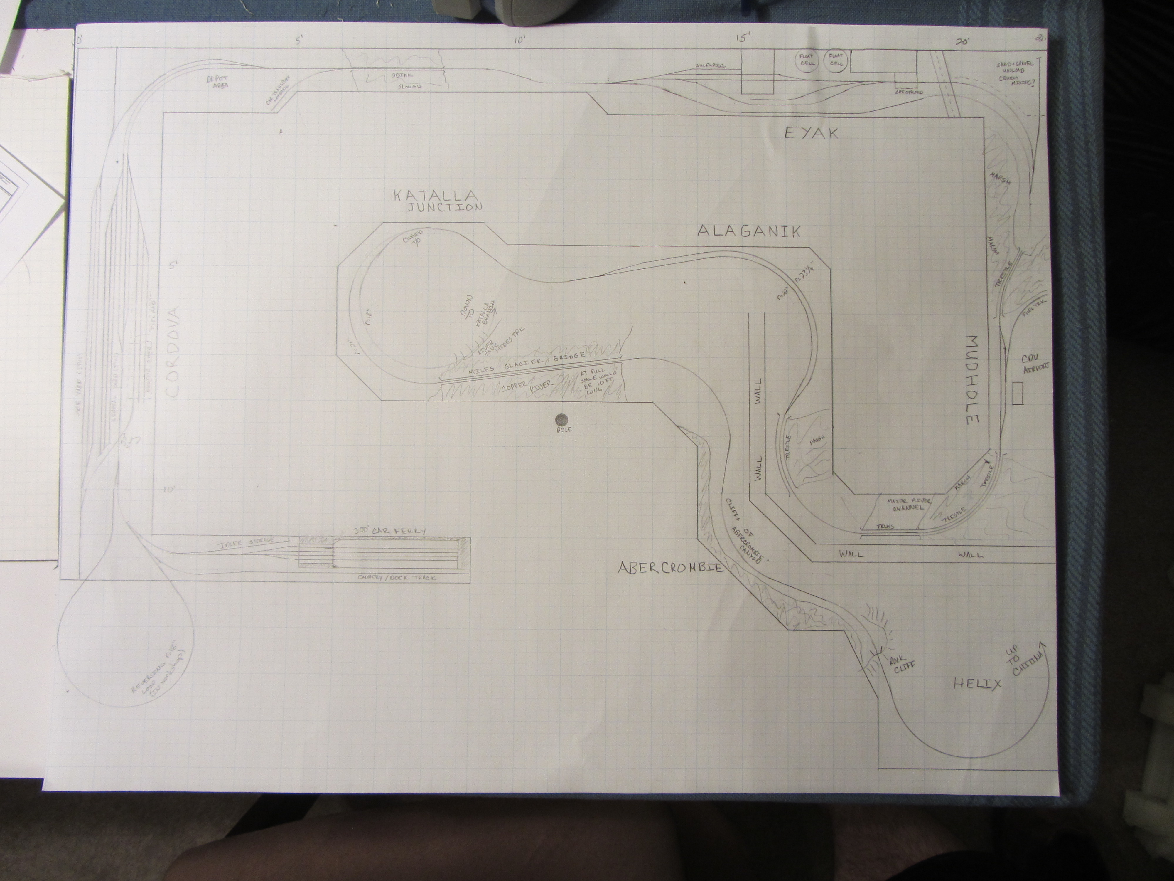
The Copper River & North Western crossed the Copper River three times on its way from Cordova to the mines at Kennicott – once across the delta on miles and miles of trestles, fill, and the occasional truss bridge, once at the famed “Million Dollar Bridge” near Miles Glacier at milepost 49, and then again northeast of Chitina at milepost 132.

Both of the lower crossings were permanent and relatively durable.  The miles of temporary trestle were slowly filled with rock where possible, making for a very sturdy embankment between more permanent trestles and spans.  The Miles Glacier bridge stands to this very day as a testament to its engineering and construction, although it did need a few million in repair work in the past decade to undo 1964 earthquake damage that dropped the last span into the water.

The last crossing, however, was never permanent.  The CRNW built the Cordova-Chitina line to a slightly better standard than the Chitina-Kennicott line, because it initially considered the latter segment to be a branch line off of a mainline that had ambitions of reaching further into the heart of Alaska.  (That, of course, never happened.)  Due to the expense of yet a third large steel bridge on what, at the time, was considered a branch, the MP132 crossing was constructed as a timber trestle with steep approach grades on both sides.  Each year the spring break-up of ice (and sometimes due to glacial lake outflow flooding – more than once a year) would take out significant portions of the bridge, and each year, CRNW B&B forces would drag out the pile driver and put it back.

What actually happened was that the 1938 trestle (the one that carried the last train on November 11, 1938) washed out in the spring ice break-up of 1939, just as expected.  It was replaced by a cable tramway high over the Copper River, which lasted into the 1960s.  In 1971, the current deck girder road bridge was completed roughly where the trestle was located, and the grade was turned into a slightly less primitive road.  The road was improved again in the 1990s, giving us the state of the McCarthy Road today.

Alternate History

Now stepping into the world of the CR&NW that only exists in my mind at the moment, and is turning into reality in my basement…   The CRNW has survived into the present day, and is still hauling ore from expanded workings around McCarthy.  Clearly some rinky-dink trestle that gets destroyed a couple times a year is not going to have survived this long.  The third bridge would have been built at some point in this alternate history – but when?

It’s likely that no bridge would have been built during the WWII era due to material shortages.  Either it would have been built in the 1930s – not likely because of the low demand for copper due to the Depression and cheaper copper available from other Kennecott properties – or in the late 1940s/early 1950s following the war.   Given that Kennecott dieselized (or electrified) many of its steam properties immediately following WWII, it’s reasonable to assume that a surviving CRNW would have followed suit.  So, for our alternate CRNW history, we’ll just say that diesels, mine improvements, and track improvements were all part of a large capital project starting around 1951, as the light rail, untreated trestles, and other such would have been in need of renewal and improvements by this point to keep the railroad safe and efficient.

Okay, so now we’ve worked out an approximate date that would be likely for construction of the Chitina bridge.  Thanks to an engineering diagram that Ron Simpson posted on the myLargescale.com forum (full-size image here) a couple years ago, I know what the original proposed (1909) Chitina steel bridge would have looked like.  The planned structure would have a 360′ Pennsylvania truss crossing the main channel on the Chitina end, followed by three 275′ deck truss structures similar to those used on the Kuskulana bridge.  The railhead would have been approximately 94ft. off the river bottom over the main channel, and 70ft. off ground level on the east end of the bridge.  We’ll take this as the baseline.

I’m torn on how to model this.  On one hand, I know what the planned structure was supposed to be.  On the other hand, the railroad lived with the temporary trestle until 1938, and per the reasoning earlier, that temporary structure may well have lived until the very early 1950s.   If a 1950 engineer was looking at the same river, would he arrive at the same conclusion as the 1909 engineer who came up with the original structure?  Or, instead, would the 1950 engineer look to newer, less time consuming and costly construction styles, such as deck girder?  Would that bridge have lasted to present day?  Just to throw another complication in there, would the State of Alaska still have built a road out to McCarthy?  Okay, okay, let’s start working through those one by one..

Various bits of data I can find from the USGS and other qualified organizations suggest that the immediate Chitina area has not received any earthquakes violent enough in the last 60 years to have significantly damaged a large, well-constructed bridge like the one proposed.  It’s simply been too far from various epicenters of large quakes (1964, 2002, etc.)  Given that railroad bridges are typically designed for 100+ year lifespans, there’s no reason that a 1950 bridge should not still be in service today.

Given other large-span railroad bridges built in the 1950s and 1960s, I have to assume that some form of truss would still be the preferred methodology.  (The Wisconsin DOT bridge manual for railroad structures still lists “truss” as the preferred type for spans over 150 feet, even in 2003.)  As for which exact truss style would be used, that’s still up in the air.  I could match the rest of the railroad and use a Pennsylvania for the through truss design, but I

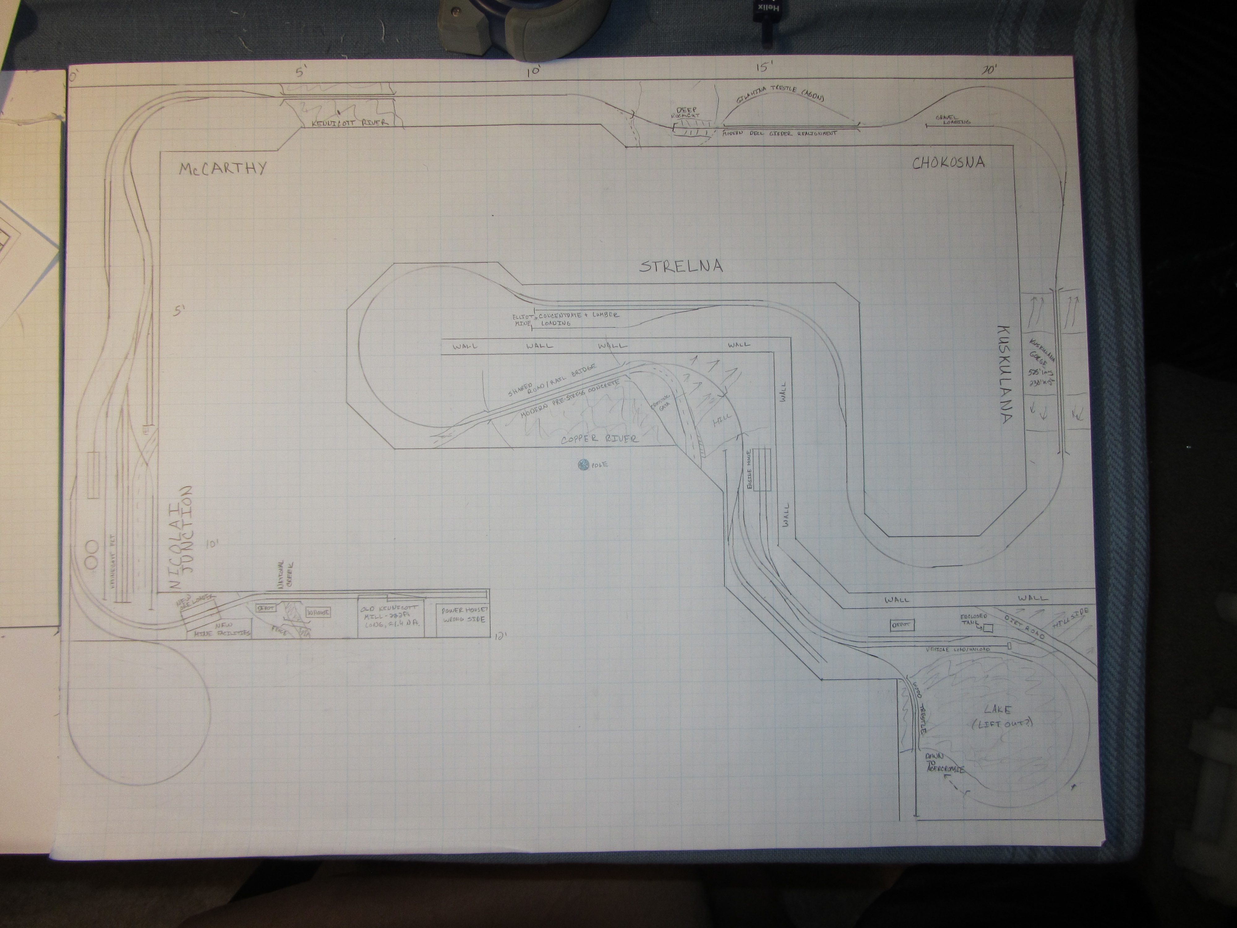
I have to assume that either Kennecott or the State of Alaska would have eventually connected McCarthy into the road system rather than being completely dependent upon rail access.  If Kennecott had built the access road, then the only logical choice is to share the road/rail bridge at McCarthy.  If the state built it, then it’s still an option.  Public data shows that even the 1971 highway bridge that exists today only saw 166 cars/day on average in 2000, and 400+ cars/day today.  That’s pretty low to justify a multi-million dollar bridge.  (I admit, I’m biased on this point.  I’ve wanted to model a joint road/rail bridge ever since seeing the combined BC Rail bridge at Fort Nelson decades ago, so I’m totally justifying myself here.)

My current thought is to go forward with the original bridge design, selectively compressed to fit within the 5 feet of allotted space that I have (the real one would have been around 8 feet), but make it a shared road/rail deck .  It’ll obviously be one lane, so we’ll add some traffic lights at both ends, and interlock them with the signal system.

It does raise the question, however – if the road and railway shared the MP132 bridge, what would they do when crossing the Kuskulana?

CRNW LED Lighting, Round 2

While I was in Indianapolis, I received a call from DHL…  They had a box from China, and I hadn’t been home for the first two delivery attempts.  Woohoo!  The LEDs for lighting the layout arrived (all 500 feet of warm white and 250 feet of cool white) early!

When I arrived back in Colorado (which turned out to be a long and annoying tale on its own – thanks a lot, United…), the other piece of the puzzle was in the mail – an RGB LED strip.  As you’ll recall, my plan was to combine two warm whites, a cool white, and an RGB strip, so that I can vary both the intensity and color of layout light.  Eventually, I plan to integrate that with the fast clock system so that over the course of an operating session, the light will change to model the real change in daylight.

While I want to get going on benchwork again this weekend, I couldn’t go get more lumber because it’s (quite unusually) pouring rain outside and I loaned my truck to a friend.  So, given that I had some power MOSFETs and a MRB-GIO sitting around, I decided to try building a prototype MRBus light controller.  Turns out it was pretty darn easy, aside from some thinking about correct snubbing on the FETs to prevent inductive kick from killing them.  I’ll post a schematic soon, but for now, I’ll show some pictures of the prototype.

In the pictures, you’ll see the MRB-GIO, the breadboard with the power drivers and snubbers, my trusty Lambda power suppy, and then the test LED strip, showing all the different ways it can be turned on and dimmed.  Then there’s also a couple photos of some early tests – I could just send intensities over MRBus to the controller, and lights would change.

This is going to work beautifully…

LED Lighting Rethought

So last night, as I was trying out various LED strip configurations, I was trying to match my old fluorescent tubes in terms of illumination without regard to overall power consumption, cost, or anything else.

Today, sitting at work, reality smacked me upside the head.  Each deck has approximately 110 feet of linear run, so 220 feet of lighting for the whole layout.  Assuming four strips of LEDs going strong for main lighting, that works out to 4.8A/4ft, or ~1.2A per foot.  That’s 264 AMPS of 12 volt power, or 3.2kW.  Yikes!  Given at a 20A house circuit can only source 2.4kW under ideal conditions, that’s probably 2-3 house circuits just to light the layout. (Remember, any power supply isn’t going to be 100% efficient.  In fact, 75% would probably be a good day.  Then, unless it’s power factor corrected, that’s going to get even worse.)  Given that my breaker box is buried in a finished wall, running new circuits would be painful.

After some tinkering when I got home, I came to the conclusion that two LED strips is probably “good enough”.  That’s only 1.6kW, which even assuming crappy power supplies should easily fit on existing circuits I can tap from the basement.  So, I ordered enough LED strip to complete the layout this afternoon…

Now off to continuing to demolish the old layout and clean out the basement for new construction.

And Construction / Destruction Starts…

Here’s a last look at the start of the Canadian Arctic Railway, my fictional bridge line from Fort Nelson, BC, to Anchorage, AK.  I started planning this line almost a decade ago, and began construction shortly after buying this house with my wife.  Then she became my ex in 2008, and the railroad went into an seven year holding pattern.

As of tonight, CR&NW plans in hand, I started tearing down pieces that aren’t staying in the new design.   The helix came out, and I’m in the process of removing the under-level staging yard.  (The staging yard is getting a new life as a testbed for some Iowa Scaled Engineering projects, so it’s still around, just shorter.)

Tomorrow or Sunday, I’ll remove the upper deck and extend the wall framing out through the area the helix once occupied.  Then comes the task of replacing the old heavy upper framework with a new, lighter open grid system.  The bottom through this section will likely remain the same – Fort Nelson is being rebuilt as the main Cordova, AK, yard.  All new construction on the bottom, however, will follow a similar lightweight construction method.  I’ll also be installing a valence above the upper deck, and shelving below the lower deck.

And so the journey begins…

Draft Track Plan

I started off this layout thinking I’d step into the 21st century and embrace CAD tools for track layout.  I’ve often been described by my friends as “CAD-tarded”, because of my long-standing and complete inability to use CAD tools.  I don’t know why, but the tools and I spend more time fighting each other than getting work done.  I guess my brain isn’t wired that way.  But, I figured with a fresh new project, this was the time to start trying again to switch from my old ways.

Wrong.

I grabbed demo versions of many of the popular packages (CADrail, 3rd PlanIt, etc.), or full versions, in the case of the free XTrkCad, and wound up beating my head against them for a full day before giving up.  I just couldn’t get things to work, and the frustration was driving my creativity level to a new low. Well, there’s a Saturday I’ll never get back.

So on Sunday, I pulled out my 17×22 quadrille pad, templates, compasses, rulers, and drafting pencil.  I was so much happier.  The creativity returned.  I spent the entire Sunday drawing, and didn’t even realize that I’d been at it for 14 hours until I looked up at the clock at 2am.  Oops.

Here’s my initial sketches of a track plan, as captured by my little camera because I haven’t yet scanned them (they’re 17″x22″, a bit bigger than my scanner bed, so it’s going to take some work).  Thoughts, comments?

My initial sketch of the upper deck track plan, from Chitina to Kennecott.  I realized after I took the picture that I'd forgotten to relabel a few things after moving things around.  Chitina is in the lower right, and Kennicott is on the peninsula on the lower left.

Upper Deck

My initial sketch trackplan of the CRNW's lower deck, from Cordova up to Abercrombie Canyon

Lower Deck