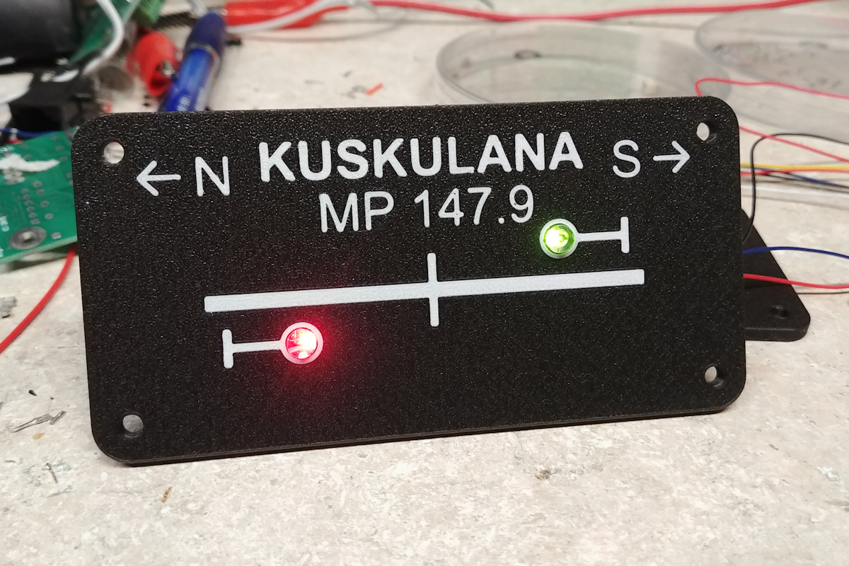
I’ve always liked the idea of fascia signal repeaters, just so operators on through trains don’t need to push to push their way into every corner just to see those inevitable awkwardly-placed signals. Is it prototypical? Probably not, although in either cab signal territory or now as we’re pushing into the new world of PTC, it’s not that far off. It just makes for a smoother operating session, in my opinion.
One option is 3 LEDs per signal head – one for each major color. That’s a lot of LEDs to make room for on the panels. Another option would be red/green bi-color LEDs, energizing both to get a mixed fake yellow color. That has the advantage of one hole per signal head, but the problem is there’s often significant variation from one LED to the next (requiring tuning the color of each individually), and they have a strong color shift based on viewing angle. What I really wanted was a true three-element LED, with true red, amber, and green emitters. The problem is that most of the very few true red-yellow-green LEDs are surface mount, which doesn’t lead itself to being installed in fascia panels.
There is one option, though – the Lumex SSL-LX5097SISGSYC. It’s a standard 5mm LED, albeit with four leads, and available off the shelf from Newark. The red and yellow are reasonably bright, but the green element is a bit weak. Still, some experimentation on the bench showed that they were more than bright enough for panel indicators, and with the proper resistors could be nicely evened out to the eye. At 5V, putting 1k on the red lead, 560 ohms on yellow, and 220 ohms on green provided subjectively even indication brightness.
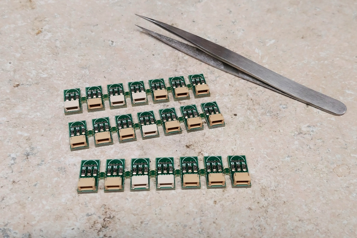
Since I didn’t want to solder resistors and leads on to something like 60 LEDs, I built a small PCB that integrated a place to mount the LED, the three dropping resistors, and a small JST SH-type 1.0mm 4 position connector. Panelized into groups of 7, it cost me $30 to have 210 individual boards made at PCBWay. After that, it was a matter of getting a solder stencil, slathering on paste, placing components, and then reflowing them in my toaster oven that’s dedicated to PCB manufacture. For those interested in making their own, the schematic, PCB, and Gerber files are all under the “ckt-sigcon” files in the ISE CKT-SIGNAL project on Github.
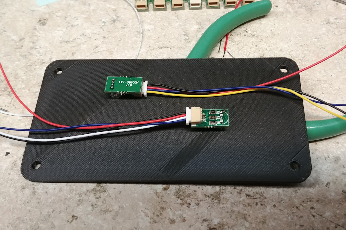
Once assembled, it was a simple matter of soldering in the LEDs and installing them in some of the new control panels that we’ve been 3D printing. Connections to the little LED boards can then be made with 4-wire cables available from a number of sources. I have a large supply, since Iowa Scaled Engineering uses them for connecting to our newest versions of the TrainSpotter detectors. However, Sparkfun also sells them for their Qwiic I2C network system, and I’m sure you can find more sources. Ours are custom made by DirtyPCBs.
The end result is a very nice looking signal repeater panel with very clear indications in both normal room lighting and in “night” mode.