Category Archives: Benchwork

Posts related to benchwork

Layout Update – Jan 22, 2021

Since I haven’t posted pictures of the whole layout in quite some time and it was all nicely cleaned up for the CR&NW’s first work night last week, I thought I’d show you the state it’s currently in. The track is complete, except for a few spurs and industry tracks that have yet to be positively defined. The backdrop and fascia is 99% complete. The lighting is done, the signaling is 95% done, and track power wiring is 95% done. I’m still installing switch machines at Chitina and Cordova, but that should be done in a week or two. I’ve also posted pictures on the backdrop to inform others and remind myself what some of the scenes are supposed to look like. It’s a combination of my photos from visits over the last decade combined with historic imagery.

Once I get those last few benchwork and electrical to-dos resolved, it’s on to scenery and painting!

Fascia Completed!

This thing is actually starting to look like a proper layout rather than just a bunch of track on 3/4″ plywood cookie cutter. At 22:30 Friday night, I joined the upper deck fascia. The lower deck took just a bit longer – 14:00 on Saturday afternoon – because I needed to wait on some brackets to print. With that, the layout fascia is complete and I can move on to cleaning up the room, finishing electrical, and starting to shape in the terrain.

Let There Be Light!

As long-time readers (or others who know me) know, I have a bit of a fascination with layout lighting and making it part of the overall operating day experience. Plus, it’s easier to work on a layout – either from a construction, detailing, or operations standpoint – when there’s excellent lighting. So in today’s post, we’re going to look at what I settled on for lighting the Copper River.

Continue reading

Attaching Fascia

Since 2020 is officially the year of not leaving the house, I’ve actually made some progress on the CR&NW. More of my time has gone to other projects, like resurrecting a 1940s searchlight signal in my back yard, but the layout is moving forward.

A dual mount point fascia bracket showing how it works

One thing that’s never been quite clear to me is how folks attach fascia board to open grid benchwork in a secure way, such that it’s solid enough to support the weight of an operator who stumbles, yet there’s enough room behind it for the mounting of controls and some modest wiring. If you just screw it straight into the front of the grid, it’s solid but there’s no room for switches and wiring. If you mount it on some standoff wooden blocks, there’s room behind, but has a lot of flex to it. Plus that’s a lot of standoff blocks to cut.

Then I realized I have a 3D printer and this seems like an excellent way to solve the problem – printed standoff brackets.

Continue reading

First Train Reaches Gilahina

It’s really amazing how long it takes to do things sometimes.  I honestly hoped I’d be where I am now almost a year ago, but hey, life gets in the way, right?

At least I’m finally making progress on the mainline.  As of 1900h tonight, the first train reached Gilahina – or at least where the new Gilahina bridge will be in the future.  Sure, the electrical isn’t complete that far out (power was provided by clip leads) and there really wasn’t any complex trackwork in that stretch, but I’m still happy that I’ve finally got mainline down and can run trains more than over a few switches.

Changing Contact Adhesives

Unfortunately I had a fair number of other things to do this weekend, so I didn’t get as much done as I really would have liked.

Typically for attaching N scale roadbed and track, I use DAP’s Weldwood contact adhesive. What can I say – it’s cheap and it works.  However, the stuff is a witch’s brew of organic solvents that – in addition to potential biological side effects – features prominent warnings about causing an explosion when being used, say, ten feet from a furnace.  During the summer that’s not an issue, since the furnace is shut down dead (and I have an electric water heater, so that’s not a concern).  Since it’s now winter, ventilating the basement adequately to avoid the “big boom” isn’t as much an option.  So I set out in search of a better adhesive that would be less likely to form a mushroom cloud in eastern Colorado Springs.

What I found was 3M’s Fastbond 30NF.  It’s still a polychloroprene contact cement, but the chemical engineering wizards at 3M have figured out how to make it primarily water-based, rather than all the organic solvents in most other contact cement.  It’s explicitly marketed for its nonflammability when wet.  In fact, the datasheet shows that it has no flash point – you literally can’t ignite it.  Sure, it’s also rather expensive ($100/gallon), but less so than blowing up your house.

The good news is that it works, and works very well in terms of bond strength.  The bad news is that “Fastbond” doesn’t live up to the fast part of its name.  It has a significantly longer wet stage than the organic solvent-based stuff, which is understandable even in such a dry environment as a Colorado winter.  I found that I usually had to wait about 20-30 minutes between application and actually being able to adhere pieces together.

The good news is that my concerns about it not bonding strongly enough (because, somehow, I assume anything not based on hideously harmful and/or flammable chemicals is inferior) were completely baseless.  The 30NF bond strength seems significantly stronger than the Weldwood, up and to the point that I had to put spacers down to keep the track from accidentally sticking when I was assembling the rail joiners.  At least twice I had a tie stick down so hard it detached from the rail when trying to get it up.  As long as it endures over time (and I have no reason to think it won’t), this stuff is superior from a bond aspect.

The other downside, besides working time, is that any frothy or clumpy spot will dry white.  However, most of that will be under ballast, and you just have to be more careful to only apply a thin layer to the bottom of the track.  Really it’s just about learning to apply more carefully than the “slather it on” method used in the past.

Nizina Yard

In 1915, the Alaskan Engineering Commission presented a report to then president Woodrow Wilson concerning the potential expansion of railroads within the Territory of Alaska.  If you want to read the report yourself, Google Books has it scanned and online.  Part of this was an exploration of potentially expansions to the Copper River & Northwestern, none of which were ever actually built.

The report proposes two branches from near McCarthy to other nearby mining districts.  One, a 14 mile branch, would extend around to the east side of Bonanza Ridge (the main Kennecott Mine was on the west side) up McCarthy Creek to the Mother Lode mine.  The other, a ~17 mile line, was proposed from McCarthy further southeast to the gold mining district along the Nizina River.

Because the Mother Lode Mine was on the opposite side of the ridge from the rest of the mines, eventually the tunnels were interconnected.  Mother Lode ore was sent through the Bonanza Mine to get it to the other side of the mountain, and then down the trams to Kennecott to be loaded.  There wouldn’t have been a reason to extend the railway around the backside of the ridge for it.  More interesting would be the Green Butte and Nicolai mines, which existed on the east side of McCarthy Creek, might have been able to use rail service.

The Nizina Branch idea is more intriguing, however.  Even while there was active mining at Kennicott, there was placer gold mining going on at Dan Creek, southeast of McCarthy and on the opposite side of the Nizina River.  Additionally, copper prospects had been described just a few more miles up the Nizina and Chitistone Rivers, along Glacier Creek.  So it’s slightly plausible that – should copper mining have survived in the district – that additional mines would have been developed on these prospects.  I don’t proclaim to be any sort of expert (or even novice of any note) in this area, but the US Geological Survey has a 1943/44 report on mining prospects in the Nizina District available as a PDF.

The short version is that I needed more traffic at the north end of the line to keep operations on the layout interesting.  I also wanted a test track above my workbench that I could use for working on equipment and programming DCC decoders.  Given that the workbench is just across the wall from McCarthy and Cordova, and that McCarthy was at just about the right height for a workbench branch, I decided the “Nizina Branch” would be born.  It will serve as staging for one empty coming up and one load going down each operating session.

The yard is three tracks wide, with the one nearest the edge being the DCC programming track in addition to storage.  Given that this is all just staging trackage, I used some leftover Atlas code 55 flex and turnouts that I had lying around.  You may notice an odd bit of 3-rail track near the end, as if I’d decided to model dual gauge.  Since I do spend a decent amount of time working on HO models for other folks, I needed the programming track to be compatible with both HO and N scale equipment.  So, using a few PC board ties and some extra rail, I built a dual HO/N scale programming section.  And yes, that’s a BC Rail B39-8 running around.  It won’t be part of the CRNW’s roster, but much like my IAIS ES44ACs, I’m rather fond of it and you’ll probably see it running around in “unofficial” layout photos.

The switch machines are, of course, my MRServo design.  They’re completely open source, but available from Iowa Scaled Engineering if you want to buy some.  The wiring is still a bit rough – I haven’t gotten it all finalized yet.  I was just happy to get the track power and programming track lines run back to the electrical panel with my limited time this week.


The Helix In Action

In between other projects tonight, I added another half-turn to the helix.  Figured I might as well enjoy it a bit as well, so ran a quick test train – just one of the SD60Ms (future CRNW 600), a half-dozen ore jennies, and a boxcar that was sitting on my bench anyway.  Figured out that an Atlas SD60M is good for about 20 cars on the 2.5% grade, based on a test I didn’t video.

Starting Trackwork on the Helix

Between Abercrombie Canyon and Chitina lies nearly 70 miles of some of the most remote, inaccessible railroad in North America.  Twisting and turning along the west bank of the Copper River, these miles would offer a great deal of scenic value, but little operational potential.  There was no industry through this stretch, and damned few people at all.  Those that were there consisted largely of native people, fishermen (largely in the lower canyon – there was once a salmon cannery around Abercrombie at MP 55), railroad workers, and of course the random outdoorsman.  From a modeling perspective, it would be miles and miles of track on a narrow shelf, perched between the mountainside and the swirling blue-grey waters of the Copper.  So,  as I needed somewhere to shift between decks, I chose these remote 70 miles to compress into the great helix.

The structure will be a 20 inch radius, 8 turn helix connecting the lower deck at 35 inches above the floor with the upper level at 60 inches.  This comes out to a grade of just under 2.5%. Inspired by other designs I’ve seen lately, I chose to use threaded rod as the main vertical supports.  It’s simple to install, requires no precision cutting on my part, and allows for adjustment after installation.

Threaded Helix SupportsThe basic design would consist of 8 sets of rods, each set 45 degrees apart and spaced by about 3 inches.  These would be mounted into a lower plywood platform and extend upward through each helix level. Thanks in part to the explosion of 3D printers on the market (which often use threaded rod for linear drives), 3/16-16 threaded rod is abundant and cheap. I picked up 16 rods, each 36″ long, from eBay for something like $40 shipped.  Nuts (part 90473A031) and washers (part 90108A032) were ordered from McMaster-Carr.

Helix 1/4 turn segmentThe roadbed itself would consist of 90 degree segments (quarter turn) cut from 1/4″ plywood, with ears at the halfway point for connecting with the rods.  Two layers of these segments would be installed for the track bed, 45 degrees offset from each other.   The segments are glued together using standard wood glue and clamped while they dry.  For the threaded rods, 5/8″ holes were drilled (very oversize for the 3/16″ rod) so that there was plenty of adjustment room.  I specifically chose large flat washers so that I could have large holes for fine-tuning the alignment.  Even though only the upper or lower roadbed segment is attached at each set of rods, this still provides a very strong roadbed once the glue sets and it’s bolted down.

IMG_1070 Starting the helix IMG_1067


Here’s a handy tip – turns out spinning a few Homemade nut spinnerhundred nuts down a few feet of threaded rod is absolutely no fun.  In fact, it’s downright maddeningly slow.  Fortunately, there’s a better, faster way to do it.  Just get a 4″ buffing wheel (meant for a bench grinder, maybe $5 at a home improvement store) and a short piece of threaded rod.  Put a big washer on each side and a couple nuts, pop that sucker in a drill, and you have a nut turner.  Makes very short work of spinning each nut down the rod.  About the only gotcha is the occasional string that gets loose from the buffing wheel and jams the nut, but that’s easily cleared with just your hand.

After that, it’s all just one step at a time.  Add a couple segments, then go back and lay track before you cover up a helix turn with the next one.  I typically have been keeping the track about 1/2 turn behind the benchwork, so that I can alternate between setting benchwork segments and laying track.

IMG_1080 IMG_1079To keep the grade constant, I built this handy grade measuring device out of a $3 Harbor Freight level.  Over a span of 8″, a 2.5% grade will rise 0.2″.  So, I had some hex cap screws lying around that had heads 0.2″ high.  I drilled a hole in one end of the level and threaded in a cap screw.  Ta da!  Almost a perfect 2.5% grade level.  I just place it halfway between each set of rods, progressively working up the helix as I build the roadbed.  I keep checking that the distance from one level to the next is a consistent 3-1/8″, but so far I haven’t had any issues using just the level method.  Once each piece is determined to be the right grade, I firmly set the nuts against the washers and the roadbed.

Helix Progress - 30 Aug 2014As of when I called a night tonight, this was the status of the helix – about halfway through the third turn.  The roadbed and track are both held on with my usual method of DAP Weldwood contact cement.  I’m out of plywood segments that have been cut, so I’m calling it a night at this point.  I’m taking Labor Day off to take in a baseball game (and then some – the Rockies still have three make-up innings against the Giants from a rained-out game last May, so tomorrow will be at least twelve innings).   Regardless, it’ll be a break from the basement.  I do plan to do some pull tests using a couple SD60Ms and ore cars to make sure we’re in the ballpark – no pun intended – of having the right grade for the trains I plan to run.

The Katalla Branch

Ever since I drew the original plans a year ago, I’d always had the idea that – should the CRNW have survived – that there might be a branch to Katalla.  As those familiar with the CRNW know, at one point Katalla was to be the terminus of the CRNW.  It had a key advantage for a burgeoning mining industry – nearby coal and oil reserves.  The town lacked one key feature, however – a natural deep-water harbor.

In reality, Katalla’s demise began with the federal government (under President Teddy Roosevelt) withdrawing public lands from coal mining in 1906.  Shortly thereafter, the lands were closed to timber and oil extraction as well.   Then, in November 1907, all of the Katalla dock and breakwater facilities were destroyed in a series of early winter storms.  With no available resources – save a single 160-acre oil field – and no facilities, the CRNW packed up and moved its terminal to Cordova.   Katalla would get a refinery to process the limited (but apparently high quality) crude it produced, but little other industry developed to sustain the town.  By 1933, when the refinery accidentally burned, there were reportedly only about 100 people still living in town.  However, that was the end – after 1933, Katalla would fade into history.

In 1971, however, new hope arose for industry in the Katalla area.  Thanks to the Alaska Native Claims Settlement Act and its effort to compensate the Alaska native peoples for their losses, the Bering River bituminous fields and the Carbon Mountain anthracite fields passed to the Chugach Alaska Corporation, one of the regional corporations set up by the ANCSA to administer lands transferred back to the native people.  In 1991, the rights to develop the field were sold to the Korean Alaska Development Corporation as part of CAC’s Chapter 11 bankruptcy proceedings.  KADCO has yet to do anything with these rights, and in fact several conservation interests have discussed buying them to prevent any future mine.

Further, the CAC obtained rights to try for commercially-exploitable quantities of oil and gas in the Katalla Field in 1982.  However, these rights were temporary, and expired at the end of 2004 unless a commercial well could be put in production.

In reality, no commercially viable oil well materialized, and the coal fields remain untouched since 1906.  However, with the idea that my modern day CRNW could provide both a customer and a transportation solution, I’m going to explore the idea that at least the coal fields were developed at a small scale.  Local coal seems a plausible energy source for both my processing plant at Eyak, the town of Cordova (which in reality today draws its power from both hydro and a large diesel plant), and the mine operation itself.  Plus, having another local job to run adds more operating interest than just the ore trains and wayfreights plying the mainline.

As much as I’d like the branch to have been developed in the 1920s or 1930s, I’d have to bend history around too much to make that plausible. If the Guggenheims and JP Morgan couldn’t get the Department of the Interior to change their mind about resource extraction in the 1910-1930 era, there’s no plausible reason to believe that it would have happened between 1930 and the transfer of the coal loads to the CAC in 1972.  So, in my version of the world, the Katalla Branch would have been developed in about 1972, once the dust had settled on the ANCSA.

One of the original 1913 Alaska Railroad Commission reports indicates that two routes were considered from the CRNW to the Bering coalfields.  Both would start near the Miles Glacier Bridge.  One route would run around the coastline to Katalla and then back up the Bering River.  The other (shorter) route would run up the Martin River delta, cross over near the foot of the Martin River Glacier, and then pass over some steep grades (estimated at 1.7-2%) and around the western shore of Lake Charlotte.  From there, it would reach the mines and could be extended down towards Katalla.  By 1972, with modern motive power, construction techniques, and the recently-reinforced knowledge of the powerful damage earthquakes could transform the coastline, I have to assume that the the mountain route via Lake Charlotte would have been used.  Plus, there was no reason for the Katalla Branch to actually go to Katalla by that point, as there wasn’t anything left of the town.

My other problem is rather pragmatic – I sketched in the Katalla Branch coming off the mainline between Alaganik and the Miles Glacier Bridge.  In reality, it would have diverged in this area, coming off the mainline after it had crossed the braided tributaries of the Copper on the north/east side of Long Island.  The problem is that’s located at the end of the peninsula on my layout, and I can’t come up with a good way to helix the track down at that point.  There’s just too much benchwork needed to support the peninsula to start putting holes in it.

I don’t intend trains coming off the branch to ever be particularly long – maybe 8 cars plus engines and caboose, to be roughly in proportion to mainline trains at 20ish cars.  Plus, back-of-the-cocktail-napkin calculations show that creating 200 tons of pure copper a day via electrowinning would take roughly 4-5 cars of coal per day, given typical generation efficiencies.  So if I could pull 8 cars out every op session, that seems reasonable to feed the whole shebang.

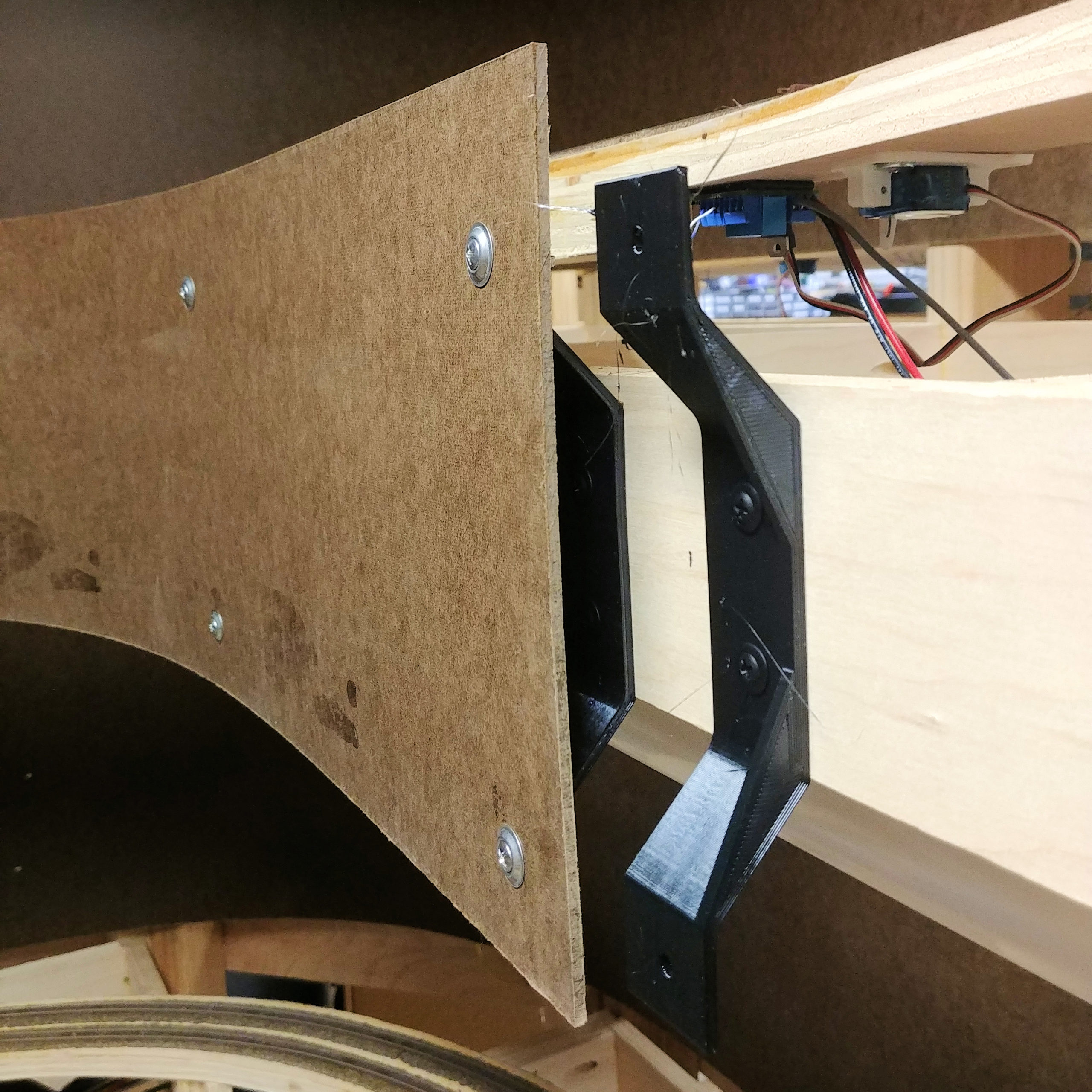
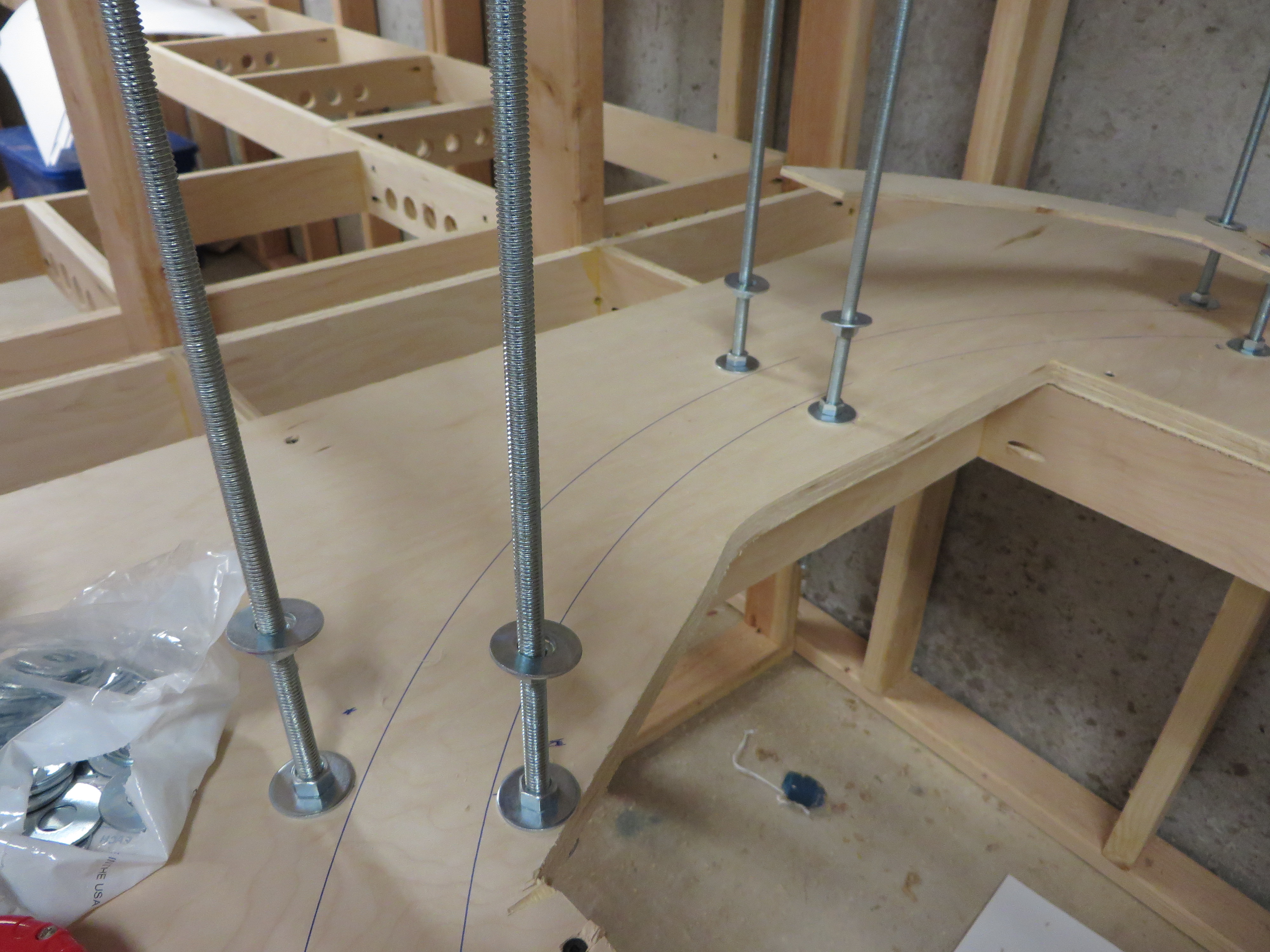
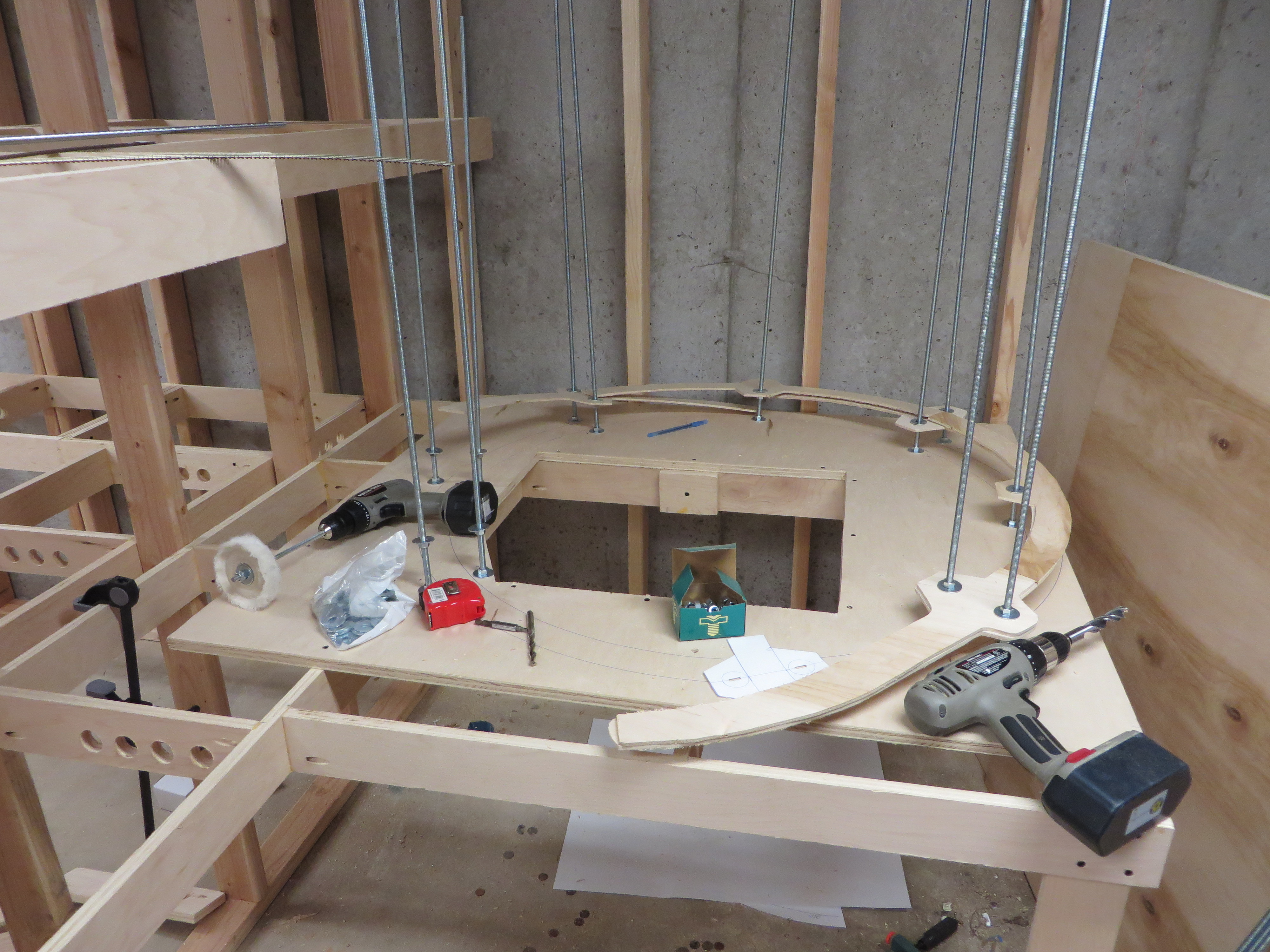
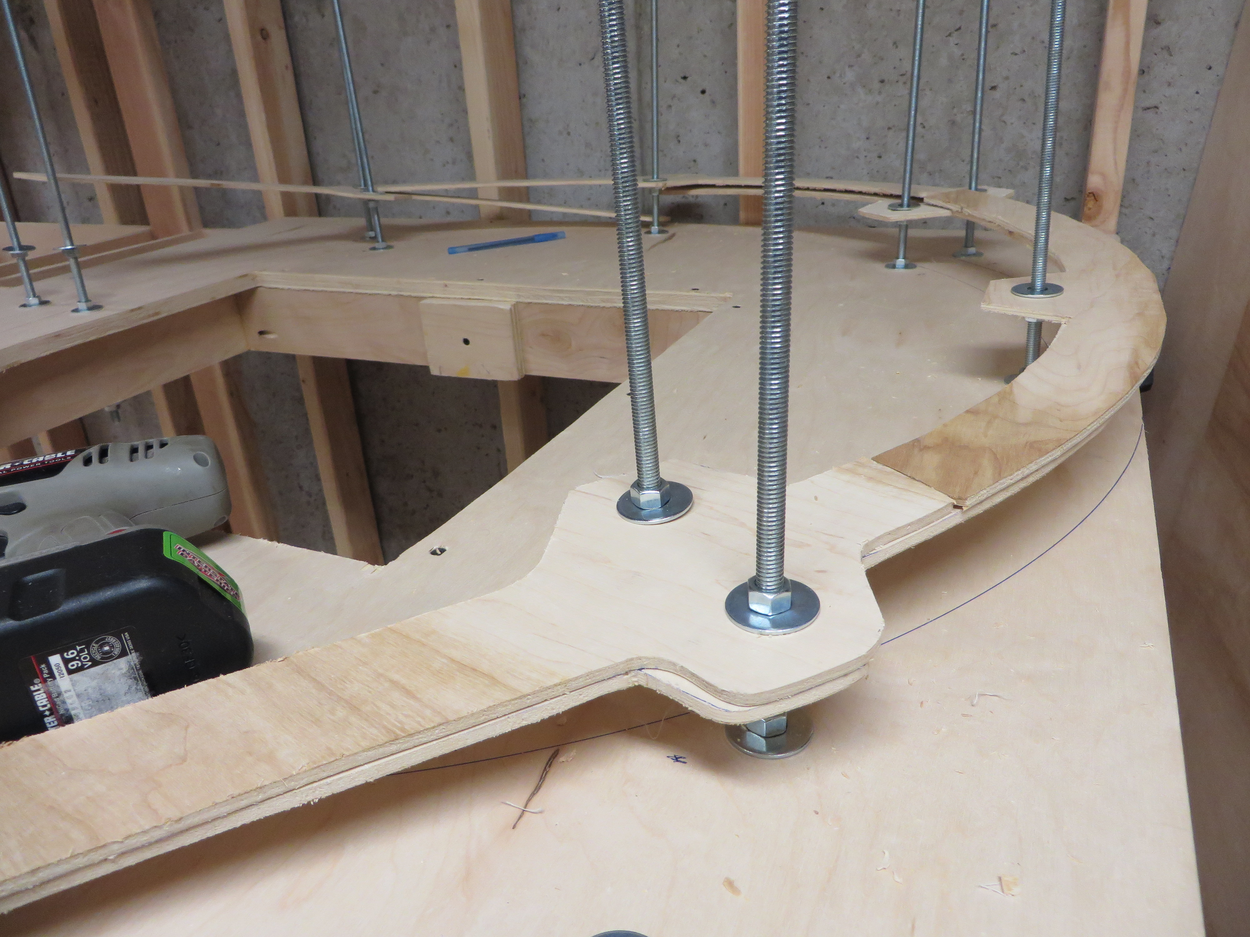
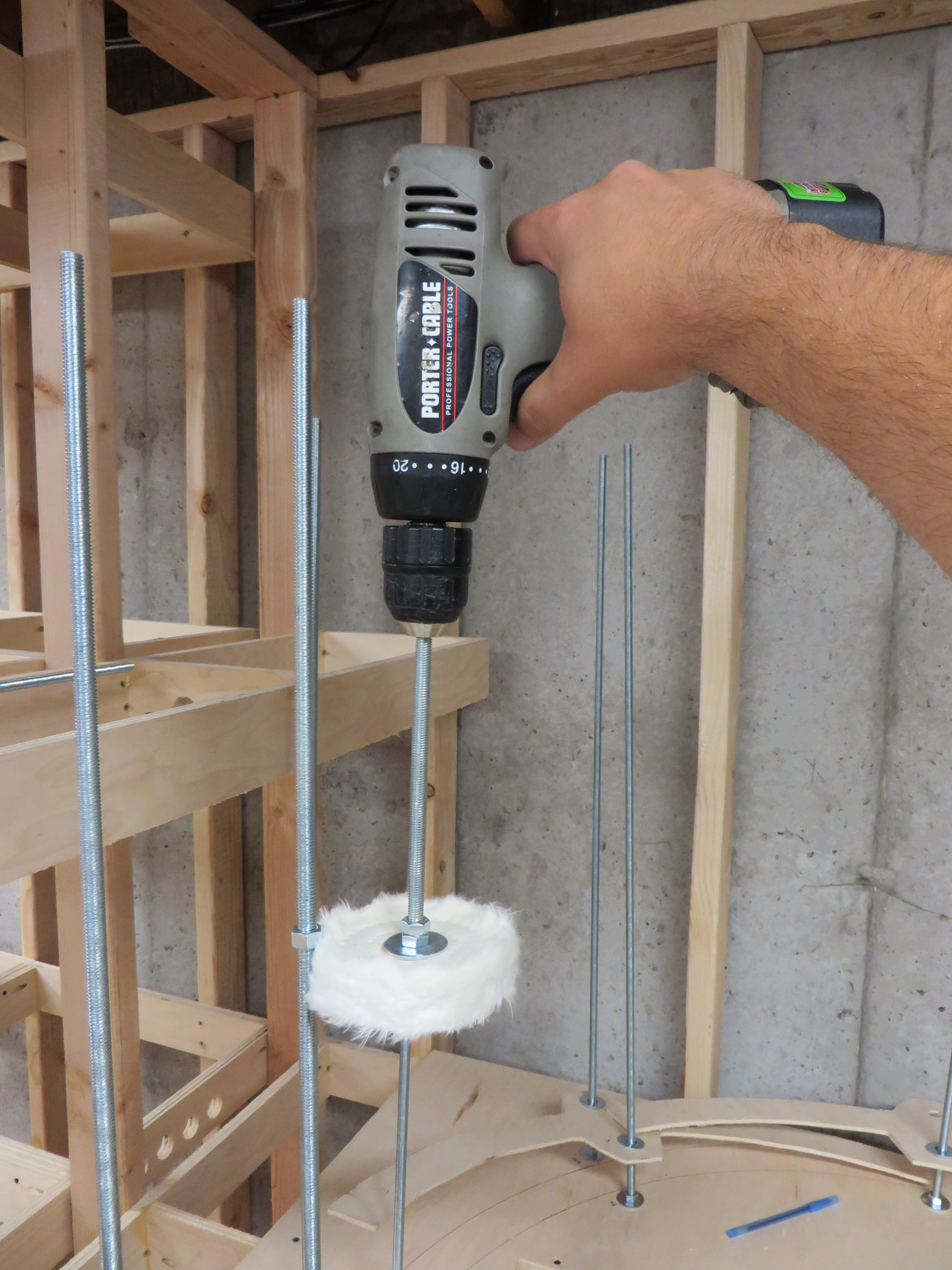
Enter the train elevator.  Basically a strip of track 55-60 inches in length, mounted to a wood carriage that rides on two linear rails.  A pair of stepper motors and jackscrews raise and lower the track between the two decks.  I intend to make it 99% automated, so that the train pulls in, power gets cut when it hits a sensor, and the elevator takes it to the other level.  From an operator’s point of view, they’ll leave Katalla Junction and disappear into the trees, and a minute or so later pop out of a summit tunnel or cut on the very lowest deck.

There’s absolutely nothing like it in the prototype.  I know and accept that.  I wouldn’t want one on the mainline – the main decks will be connected via a proper helix – but it seems an acceptable way to add time (otherwise the supposedly 38+ mile branch would only be maybe 15 feet long) and an easy connection to what amounts to a long industrial spur.  It gives me a plausible connection to local fuel producer, and a reason to run another local job every op session or two.

I’ve got the rails, the screws, and the stepper motors – now it’s just a matter of getting all the other widgets (screws, brackets, etc.), designing some controls, and testing it out.  I’ll let you know what comes of it.