Category Archives: Uncategorized

Mail Call – Snowsheds

Today’s old photo is of the snowsheds over the line, as shot from what appears to be the fireman’s cab window. The lower part of the line receives unbelievable amounts of snow, and where it ran along the steep banks of the Copper River, avalanches were a frequent occurrence. This is the only photo I’ve ever seen of what I believe to be four snowsheds along the Abercrombie Rapids section of the Copper River, just to the north of Miles Glacier bridge.

But there’s the nagging question of which locomotive is it?

That box with the tube sticking up visible at the bottom part of the frame is unmistakably a slide valve on top of a piston, which means this is an early locomotive. Of the CRNW fleet, slide valves limits it to the 0-4-0Ts, 20-22 (23 appears to have piston valves, or perhaps acquired them later in life), 50 (and likely 51 if it existed), and 100-102.

The bevel below the slide valve box into the main cylinder removes the 20s, 50, and the 0-4-0Ts from consideration. So it’s probably one of the 100s, but then there’s the two foot ledges you can see in the picture. That doesn’t fit any of them that I’ve seen pictures of, so perhaps we can’t really tell which engine this is. Thoughts?

Looking south from the cab towards four snowsheds in the lower parts of the Copper River canyon, likely between Abercrombie Rapids and the Miles Glacier Bridge

CRNW Layout Cab Ride – Feb 7, 2021

I was cleaning part of my workbench today and ran across the camera car I hacked together back in 2016 to do my original “tour around the layout” video. I wouldn’t call it a great camera, but it’s relatively small and it produces okay video for its size. My other option was keep installing switch machines and track wiring in the Eyak smelter yard, so putting together an updated cab ride sounded like more fun.

Unlike the last one, which started at Kennecott, this one will start out on the (fictional) Nizina Branch and enter the main line at Nicolai Junction (again, fictional, and between McCarthy and Kennecott). The Nizina Branch is located above my workbench, and provides some staging room and a little more operational variety for ore trains from “other mines” up around Dan Creek.

From there, it’s an engineer’s view all the way to Cordova. Stay tuned at the very end for a couple bloopers. Turns out my camera car is far wider than the loading gauge for a typical N scale car and a bit top-heavy, so it doesn’t always behave itself now that some of the layout clearances have gotten a bit tighter.

True Red-Yellow-Green Signal Repeaters

I’ve always liked the idea of fascia signal repeaters, just so operators on through trains don’t need to push to push their way into every corner just to see those inevitable awkwardly-placed signals. Is it prototypical? Probably not, although in either cab signal territory or now as we’re pushing into the new world of PTC, it’s not that far off. It just makes for a smoother operating session, in my opinion.

One option is 3 LEDs per signal head – one for each major color. That’s a lot of LEDs to make room for on the panels. Another option would be red/green bi-color LEDs, energizing both to get a mixed fake yellow color. That has the advantage of one hole per signal head, but the problem is there’s often significant variation from one LED to the next (requiring tuning the color of each individually), and they have a strong color shift based on viewing angle. What I really wanted was a true three-element LED, with true red, amber, and green emitters. The problem is that most of the very few true red-yellow-green LEDs are surface mount, which doesn’t lead itself to being installed in fascia panels.

There is one option, though – the Lumex SSL-LX5097SISGSYC. It’s a standard 5mm LED, albeit with four leads, and available off the shelf from Newark. The red and yellow are reasonably bright, but the green element is a bit weak. Still, some experimentation on the bench showed that they were more than bright enough for panel indicators, and with the proper resistors could be nicely evened out to the eye. At 5V, putting 1k on the red lead, 560 ohms on yellow, and 220 ohms on green provided subjectively even indication brightness.

Since I didn’t want to solder resistors and leads on to something like 60 LEDs, I built a small PCB that integrated a place to mount the LED, the three dropping resistors, and a small JST SH-type 1.0mm 4 position connector. Panelized into groups of 7, it cost me $30 to have 210 individual boards made at PCBWay. After that, it was a matter of getting a solder stencil, slathering on paste, placing components, and then reflowing them in my toaster oven that’s dedicated to PCB manufacture. For those interested in making their own, the schematic, PCB, and Gerber files are all under the “ckt-sigcon” files in the ISE CKT-SIGNAL project on Github.

Three ckt-sigcon panels assembled and ready to go on the bench.

Once assembled, it was a simple matter of soldering in the LEDs and installing them in some of the new control panels that we’ve been 3D printing. Connections to the little LED boards can then be made with 4-wire cables available from a number of sources. I have a large supply, since Iowa Scaled Engineering uses them for connecting to our newest versions of the TrainSpotter detectors. However, Sparkfun also sells them for their Qwiic I2C network system, and I’m sure you can find more sources. Ours are custom made by DirtyPCBs.

Two signal repeater LEDs installed in the back of one of the panels. I was experimenting as to which side I wanted the LED mounted on, hence why the two boards are on upside down. I settled on the upper configuration – with the parts toward the panel – being the preferred orientation.

The end result is a very nice looking signal repeater panel with very clear indications in both normal room lighting and in “night” mode.

The signal repeater panel for the Kuskulana intermediates, which will be located at the south end of the bridge.

New Control Panels

Now that the fascia is all there, it’s time to start mounting control panels. This is one of those things I’ve been agonizing about for some time. My traditional method involves printed track diagrams sandwiched between two pieces of acrylic and bolted into the fascia. I’ve never liked it, because inevitably the acrylic gets scratched or cracks, the print on the paper fades or the paper yellows, and they’re just a pain the butt to actually build because of all the cutting and drilling that must be done precisely.

Michael came up with a novel idea when I was visiting ISE World Headquarters a few weeks back. Basically the whole thing is 3D printed, and the track and lettering is printed using a different filament color. We don’t have a Prusa i3 with the multi-material upgrade yet (it apparently shipped today), so filament changes are currently handled manually. However, the holes are just made as part of manufacturing, and since the track and lettering is literally molded into the panel as part of the print process, it’s almost indestructable.

Here’s the Chokosna lumber reload spur panel…

Right now, we’re printing them using white and “glint grey” PLA on a textured Prusa bed to give it a finished texture. The indicator LEDs (amber for turnout position, white for timelocks, other colors to come…) are 3mm pre-wired LEDs I found on Amazon.

Five Years Ago

My phone and Google reminded me this week that five years ago, I was up in CR&NW country at Kennecott. Alternately seems like ages ago and yesterday all at the same time.

The preserved McCarthy station building, now the local museum.

Progress!

Believe it or not, I’ve actually made progress again. I have a near-final design for the Cordova main yard and have started actually putting down track.

Don’t believe me? Here’s a picture! The barge slip will be to the left, the front half of the engine shop is represented by the eSun plastic box, and the main classification yard will be in the lower right. At the rear will be four storage tracks for ore trains and passenger equipment between runs.

See – progress in tracklaying!

As usual, nothing’s easy. I just ordered every left-hand turnout I need from MB Klein, but there seems to be a bit of a shortage of Atlas #7 right turnouts at the moment. Going to call some of my usual sources tomorrow and see if I can’t scare up about a dozen of them.

Regardless, I should be able to prioritize use of the few RH turnouts I have and at least get the mainline plumbed through. At long last, more than half a decade after I started this project, I’ll finally have a finished mainline. Then I can move along to fascia and scenery.

Progress Again, Finally…

At long last, I’ve finally had some time to get back to the layout.  Over the last 16 months, work has kept me on the road almost continuously.  Also, since I last posted, I’ve had other various calamities taking my time – most notably as far as the railroad’s concerned, baseball and softball-sized hail destroying two of my cars and the entire south side of my house (July 28th, 2016).  Unfortunately one of the broken windows was into the basement, allowing torrential rain and some truly epic hail through, damaging some of the benchwork and generally flooding the basement.   I was supposed to leave to Memphis the next day, so I pretty much vacuumed up the water, dried off the benchwork, replaced the window glass, set up some fans, and shut the door.

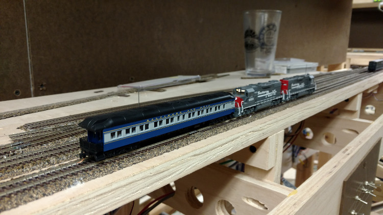
And that was  it.  That was the last time the layout was even powered up until about a month ago.  However, winter’s nearly here, work is settling down a tiny bit (though again, I’m writing this on a flight back from Amsterdam), and I didn’t really want to do anything I *should* have been doing.  Plus, the other half of Iowa Scaled Engineering – Michael Petersen – needed somewhere he could test our new Proto-Throttle that had a full-on NCE Power Pro system.  So, I dusted off a few things, cleaned the track, and brought my happy tiny universe back to life.

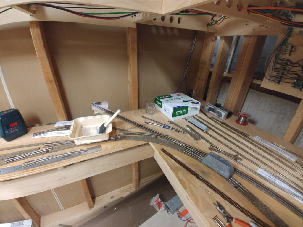
The good news is that mainline rails have now been extended from Alaganik through the airport (Merle K. “Mudhole” Smith Airport – aka CDV – which was built by the Army Air Corps in WWII on the former right of way) up to the south siding switch of Eyak, where the siding comes back in before the Eyak River bridge. 

As far as I know, there was no actual siding at Eyak.  Quite frankly, it was too close to the north/east end of the Cordova yard to justify a siding on a railroad with so little traffic.  However, in my modern day version, it’s a place to stash inbound trains while the yard is busy, or give the Eyak smelter switcher somewhere to get out of the way while mainline traffic passes.

Now the downside…  I had the entire smelter complex laid out with boxes sized for the structures and paper track templates.  It, unfortunately, was right below the broken window and had an actual torrent of water flowing over the plywood.  So all of that planning?  On the floor in a jumbled order.  I now need to go back and figure out what I’d planned, as it was significantly different than what’s on the initial paper track plan from three years ago.

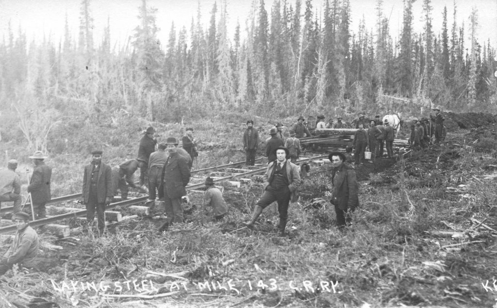
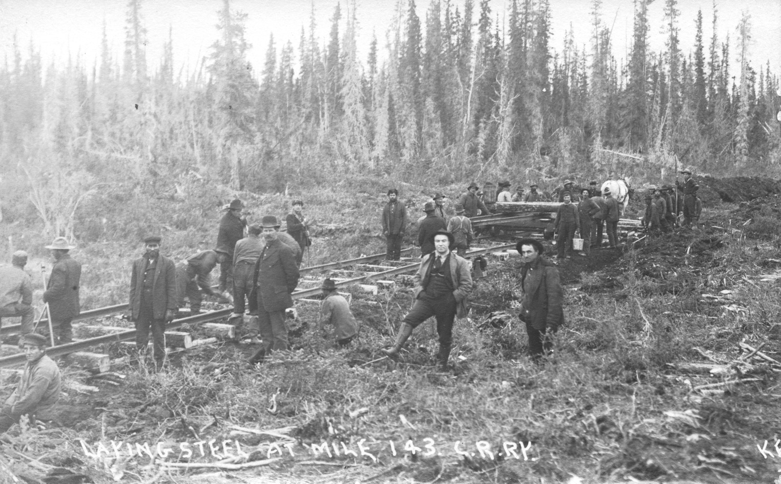
In the spirit of construction, I’ll leave you with this image of the CRNW under construction.  This is at milepost 143, or about 3 miles west of Strelna.  For a railroad that built such immense and durable features as the Miles Glacier or Kuskulana bridges, it’s really fascinating how lightly graded and constructed the initial construction of the track really was – particularly on the Chitina-Kennecott section.  Other construction photos down towards Cordova show a gravel base under the tracks, whereas this seems to be “scrape some dirt and throw down some ties”.


Power to Alaganik

In between chores around the house, I spent some time this weekend getting the power and data run to Alaganik.  Track power and detection has now been extended from Katalla Junction down to the south siding switch Alaganik.  Track is still complete to nearly Eyak – I haven’t done anything on that in several weeks now.  I’m hoping to spend some time with the signal system in the coming weeks, as well as get the mainline extended all the way into Cordova.  Much of that shall depend on how much spare time my job allows me.

In celebration of that, I thought I’d share this old postcard view of Alaganik (apparently sometimes spelled Alaganic by some in the early days).

Postcard showing Alaganik

Also, the railroad has apparently always called it Alaganik, with a ‘k’, as evidenced by this 1910 timetable:CRNW Timetable #2 - Oct 16, 1910

Happy Monday, everyone!  (Ack, back to work…)


A Video Tour of the CR&NW

So I got out a little camera I had lying around tonight, built a photo flat car out of an old flat and some six wheel passenger trucks, and put a couple GP38-2s to work pushing it around the layout.  The track is in from the Kennecott Mill all the way down to Eyak, but it’s only powered as far as Katalla Junction right now, so that’s as far as we went.

Come imagine for a moment that you’re on the back of the CRNW’s business car with me, traveling the “Plywood Pacific” that is the CR&NW as it currently exists.The CR&NW Business Train

Forgive the basement mess, it’s been a very active construction zone for weeks now, and as such is a bit of a disaster.

Link to the video on Youtube

Status Update: Not Dead Yet

There have been few posts lately because, honestly, I haven’t had the time.  My day job has involved a tremendous amount of travel to Europe over the last six months for something we’re working on, and I’ve barely been home.  That doesn’t mean I haven’t gotten any railfanning done, or spent time thinking about the CR&NW, but when it comes to laying track and wiring things, progress has been humble at best.

Two Intercities departing Amsterdam Centraal one afternoon

At long last, it looks like I might be home for three weeks in a row, so I’ll try to get an update posted in the next day or two detailing the progress that’s been made and where we’re going next.