As many of you know from my previous post, I recently converted from Lenz to NCE, largely for the wireless throttles. Despite that, I’m going to put in fascia cab bus jacks just in case. While I don’t have any intentions of running the layout with wired throttles under normal conditions, I can foresee a day when it might be necessary. The last thing I want is to have to cancel an op session because one of my neighbours cranked up their 900MHz cordless phone and took down the wireless throttles.
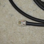
The one thing I don’t particularly care for with NCE is the use of 6p6c (often incorrectly called RJ11, RJ12, or RJ25) connectors for the cab cables. You know, those little modular connectors commonly associated with phones. And it’s not just NCE – everybody seems to have gone to these now.
Why don’t I like the 6p6c modular connectors? I find the little plastic tabs hard to release from the jacks, that they often break after any significant use, and that wiring fatigue and failure often happens near the jack as a result of inadequate strain relief. Just a month ago I was at an operating session and we had two different operators lose control of their trains because the cable failed right at the 6p6c connector.
It’s not (just) a personal dislike based on anecdotal evidence. Often times manufacturers of 6p6c jacks don’t rate the number of insertion cycles, and those that do generally have minimum lifetimes in the 300-500 insertion range. Modular jacks just weren’t designed to be plugged and unplugged repeatedly. They were designed in 1975 by Bell to provide a cheap, uniform connector for telephone cords. Telephones don’t get plugged and unplugged all that often, unlike a guy following his train around the room.
The good news is that there’s a superior connector out there. The 5-pin DIN connector, standardized as DIN 41524, was designed originally for connections between audio equipment. The connector itself has robust pins and can easily be moulded to a cable with an integral strain relief. There’s no little plastic tab to break off. Plus, even the cheapest jacks are rated for 1000+ insertion cycles, double or more what the RJs can handle. I first encountered it years ago when I was using CTC-16e as my command control system, and I was pleased that Lenz had used it when I first moved to DCC.
NCE offered a dual DIN fascia panel at one time (the NCE UTP-DIN), but apparently they’re out of production and no longer available. (Update: I’m told via the NCE Yahoo group that they’re just out of stock, not necessarily discontinued as many of the retailers state. Apparently Tony’s Train Exchange has placed an order for 500 of them and should have them soon.) Lenz still offers the LA152, but they’re rather pricey ($25-35 typically) when they’re not out of stock. Apparently everybody else has decided they can live with the god-awful little RJ connectors. I can’t.
As Usual, Build My Own
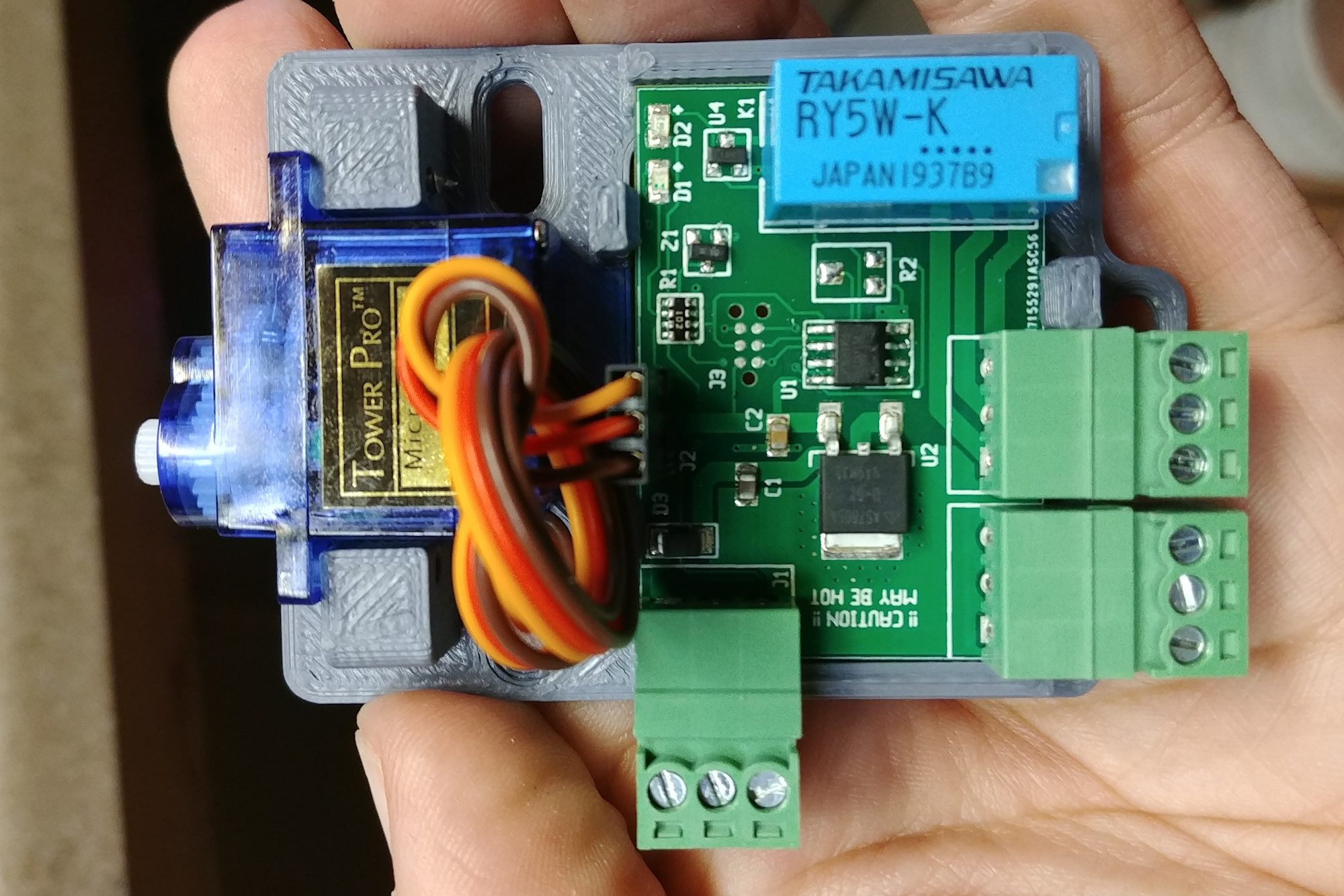
That left me with – as usual – only one option that I was happy with: design and build my own. Fortunately, the cab panels are extremely simple – just a couple jacks for the cab bus, a couple DIN connectors, some mechanical board-to-faceplate bits, and a “cab bus power” LED.
Building my own allowed me to make a couple improvements. The biggest change from the NCE version is that these use 8p8c (RJ45) connectors for the cab bus that follow the NCE Cat5 pinout. I also added a self-resetting polyfuse and a terminal block for injecting power into the cab bus, should it be needed, along with a jumper to select whether to inject power or just pass it along. This replaces the 1/8″ audio plug on the back of an NCE panel where power can be injected, and adds a bit of protection (the polyfuse) against shorts.
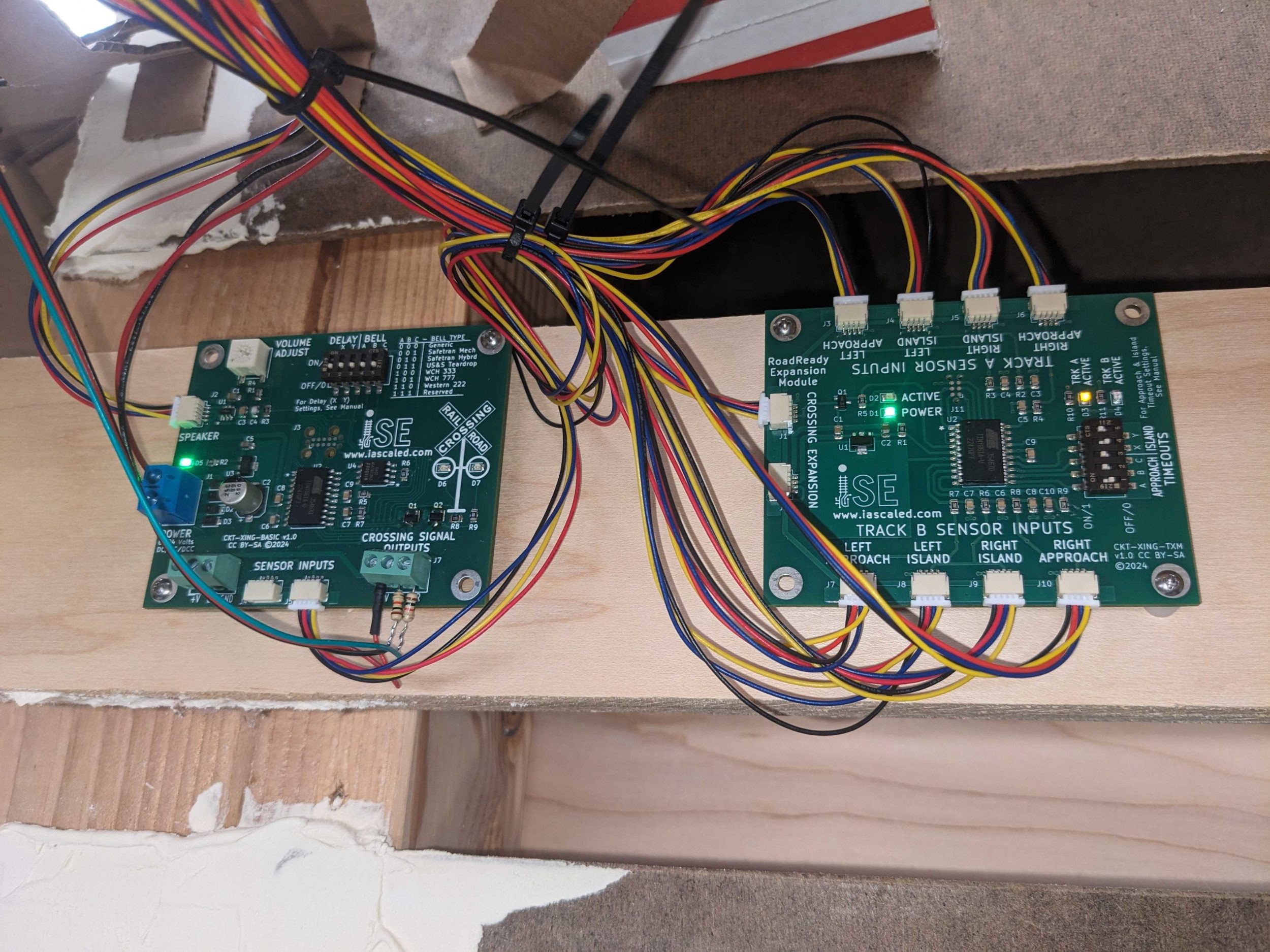
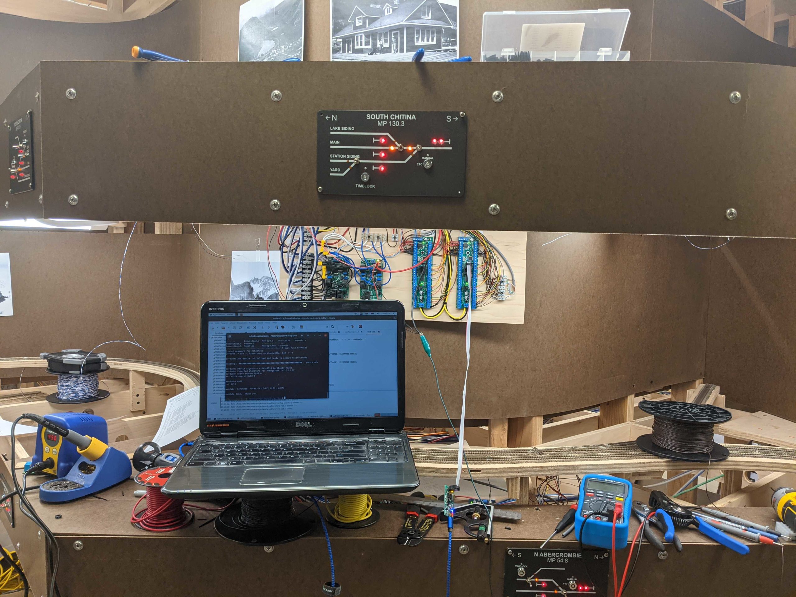
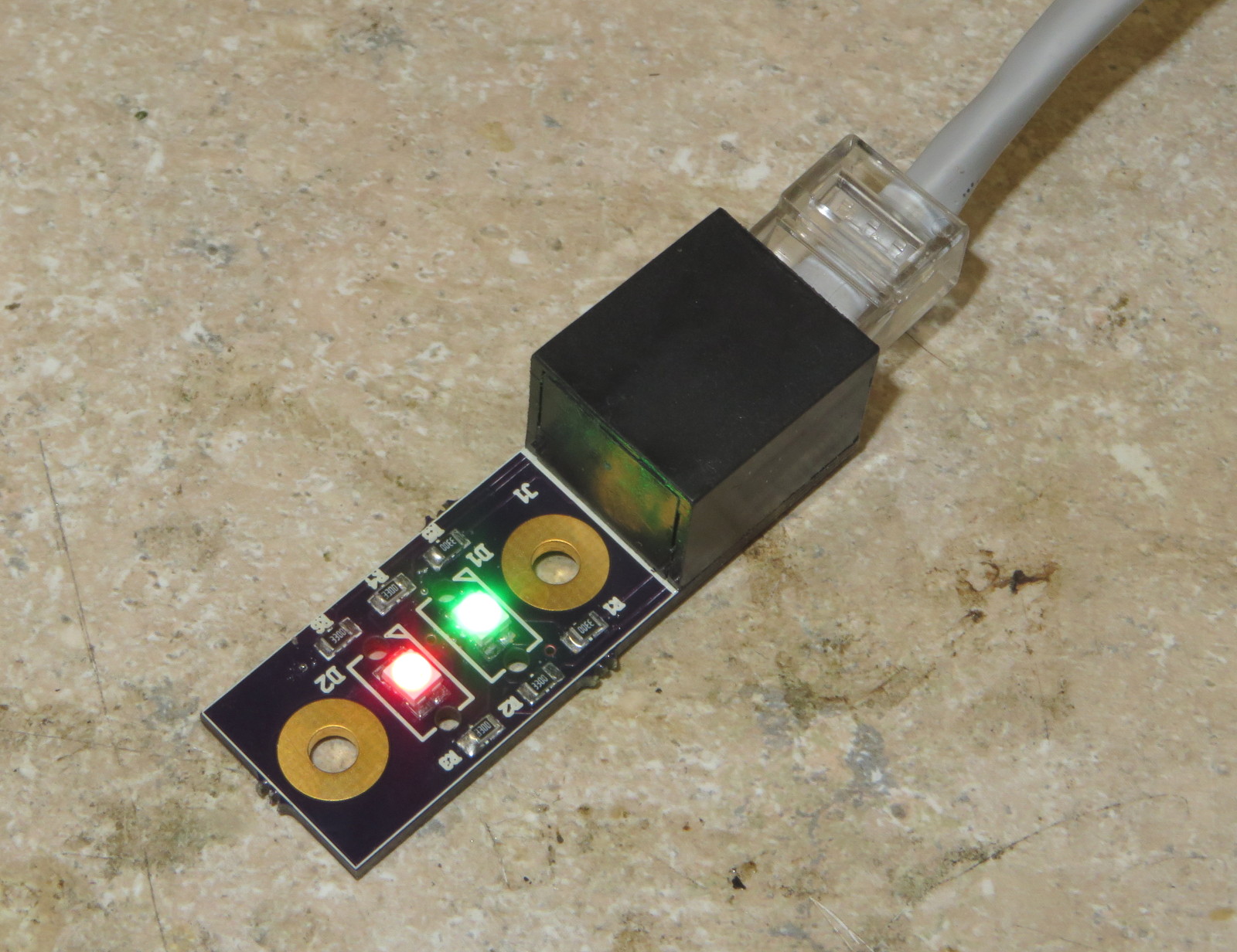
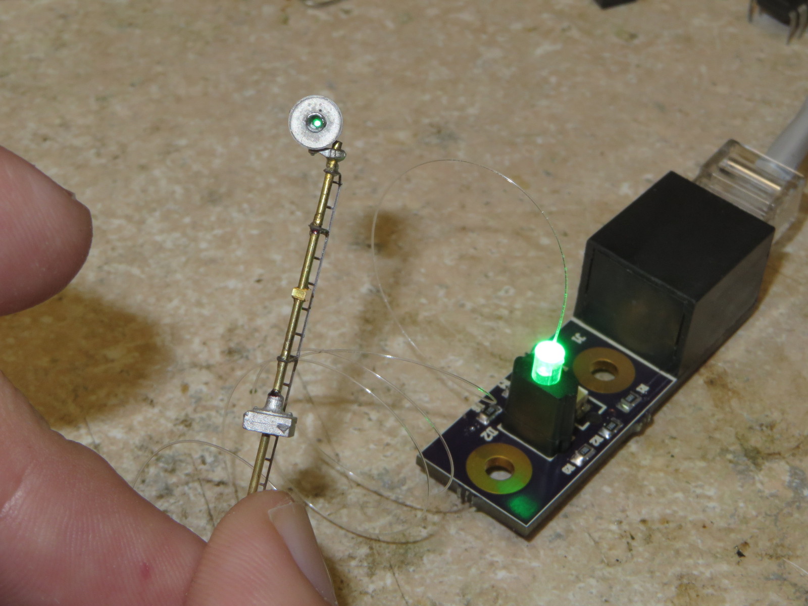
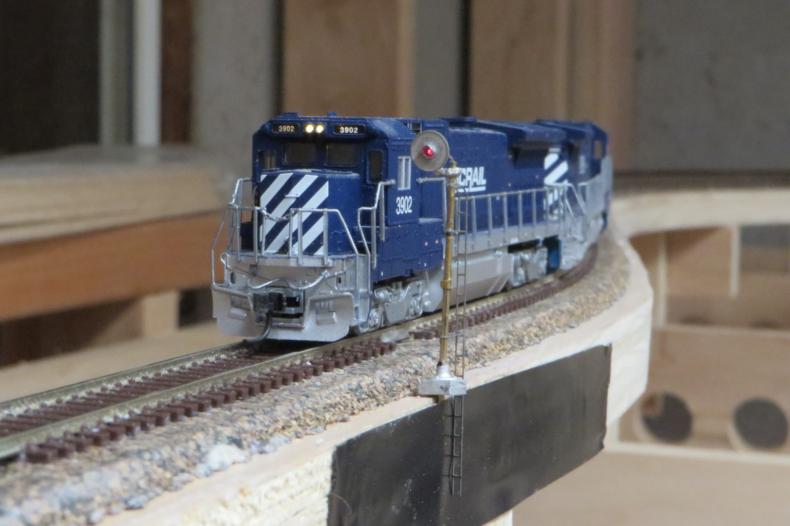
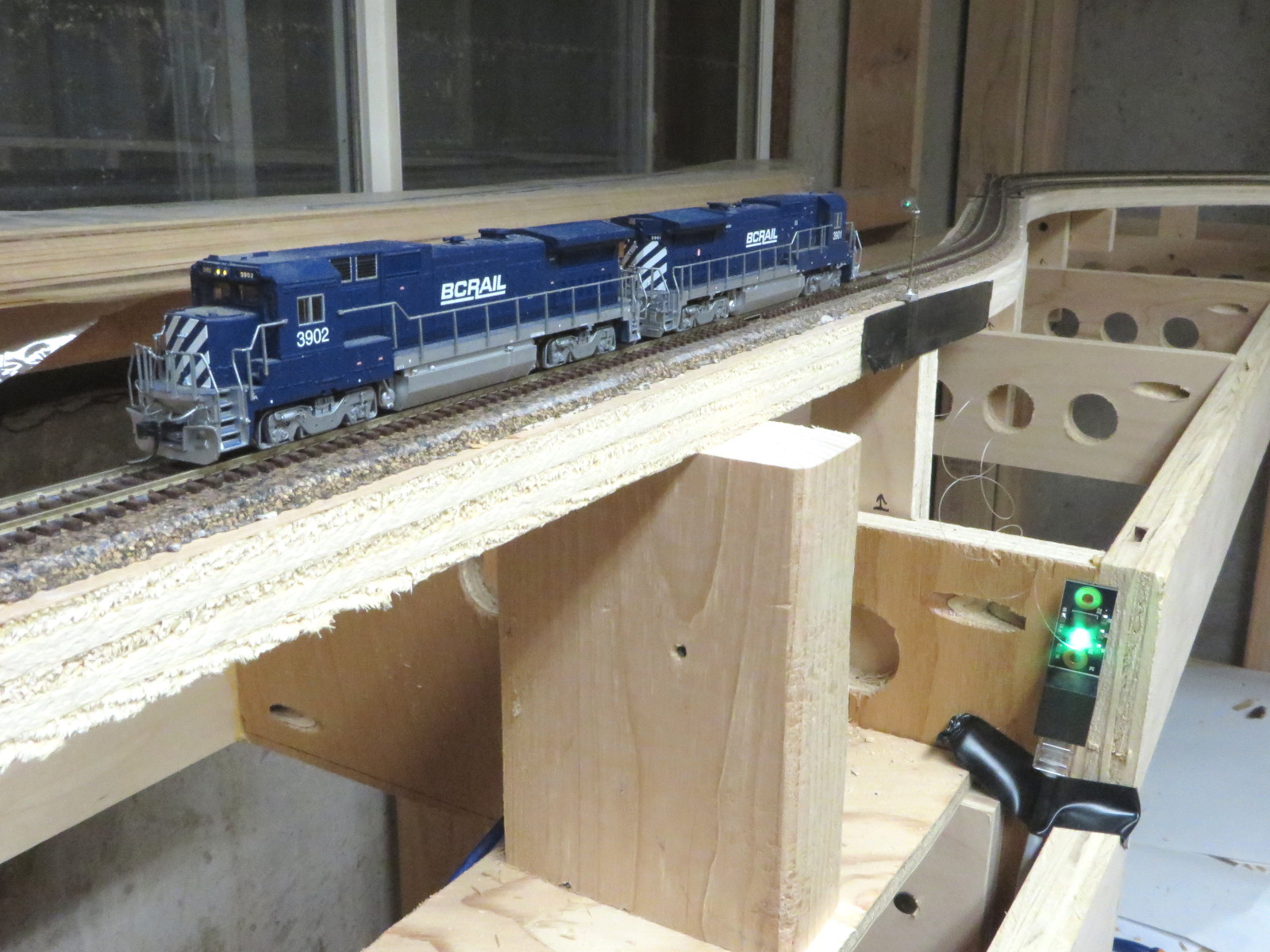
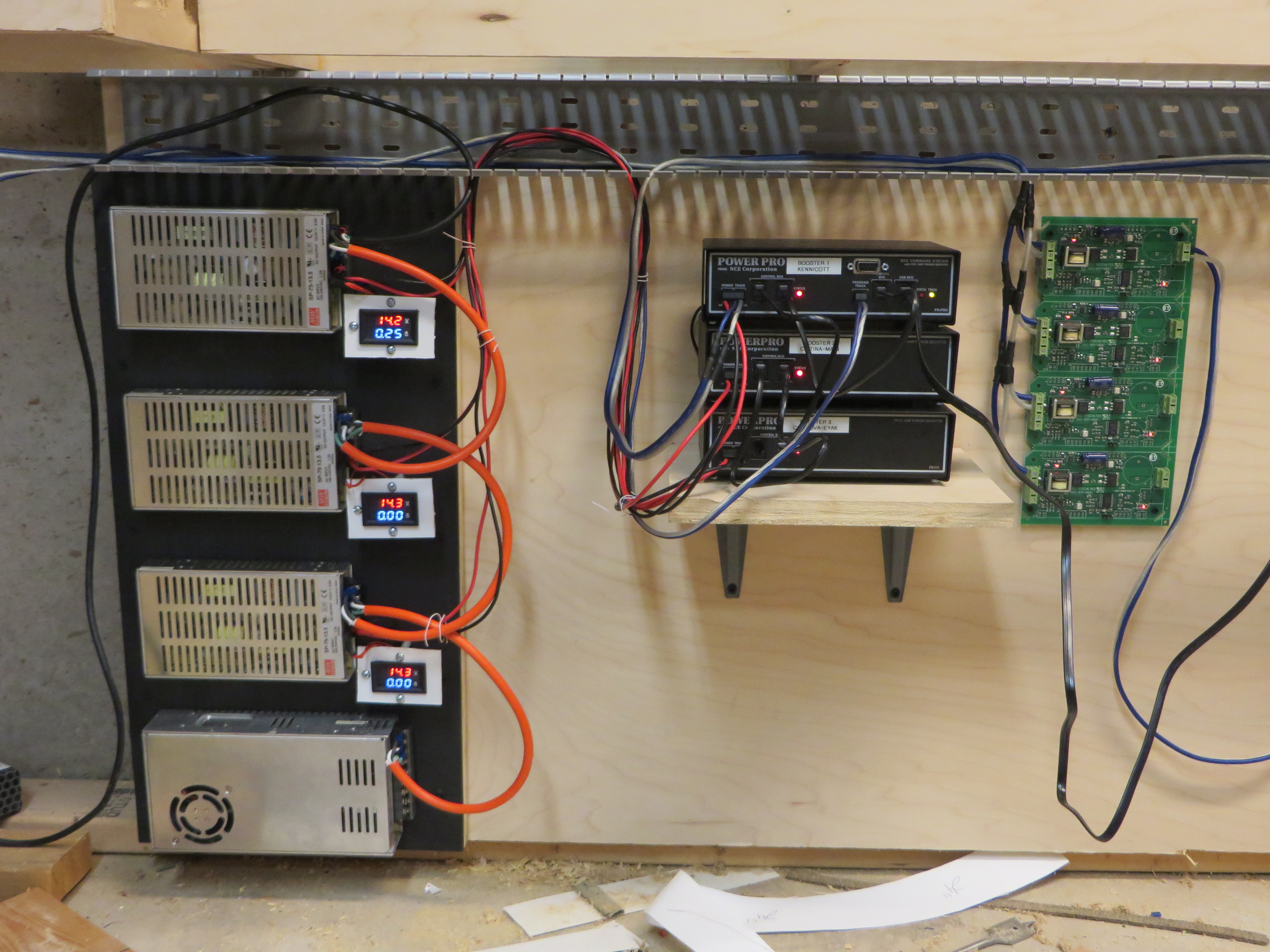
Here’s a few pictures of the first assembled prototype, plugged into the CRNW’s cab bus a few hours ago:
As a ardent supporter of Open Source Hardware, this project will be released under a Creative Commons BY-SA 2.0 license, just like everything else I build personally. (Yes, the board says Iowa Scaled Engineering, but given that I am half of ISE, I can do that…) That license basically means that as long as you give me credit for it and you share any modifications you make likewise, you’re welcome to do whatever you want with the design.
For the prototypes, I’ve sourced the panels through a PCB prototyping service called OSH Park. I use them for all sorts of things, and they do high quality work. If you just want some v1.1 boards just as they are, you can order them directly via this link. You’re also welcome to use the design files below to create your own gerbers and have them made through whomever you’d like. The schematic and PCB are designed using the popular open source gEDA suite of design tools
Design Files and Bill of Materials
Schematic (PDF – v1.1 / SVN r1114)
PCB Images (PDF – v1.1 / SVN r1114)
Design Files (gschem/pcb – v1.1 / SVN r1114)
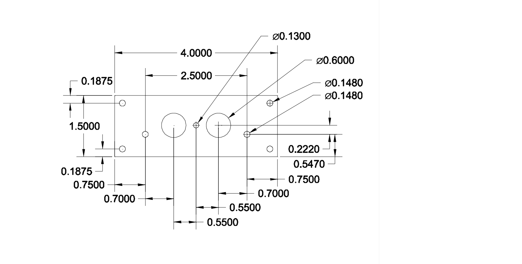
Faceplate CAD Drawing (DXF or PNG)
Faceplate CAM File (Cambam)
[table “” not found /]
Notes:
Note 1: F1 and J4 may be omitted if you do not intend to inject power at this cab panel. Also, see note 2.
Note 2: J5 and the shunting jumper that goes in it (part 3M9580-ND) may be omitted if you don’t want to ever change if a panel can inject power or not. Just solder in a small piece of wire to permanently connect the proper two holes in the board.
Note 3: There’s nothing magical about most of these parts. The Digikey part numbers are provided as a reference, but pretty much everything except the DIN plugs are commodity parts that can be found from many sources and from many suppliers.
What About DIN Cables?
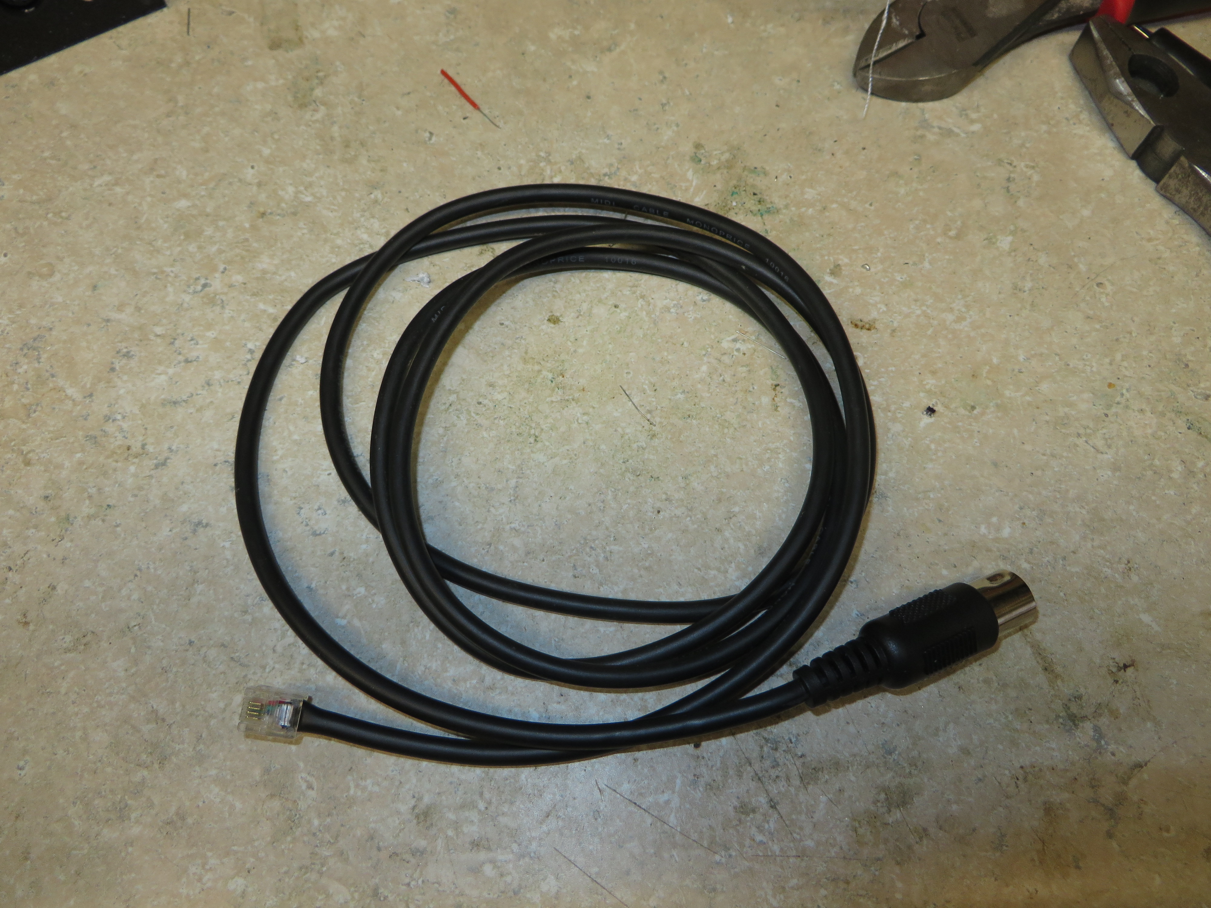
The other half of using DIN plugs in the cab fascia is that you have to actually have to have cables to connect them to the throttles. The standard offering from NCE has a 90-degree plug at the end. Again, while it should work with my panels, it’s not my favorite. I’m also not a huge coiled cord guy – I find they often get all tangled up.
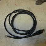
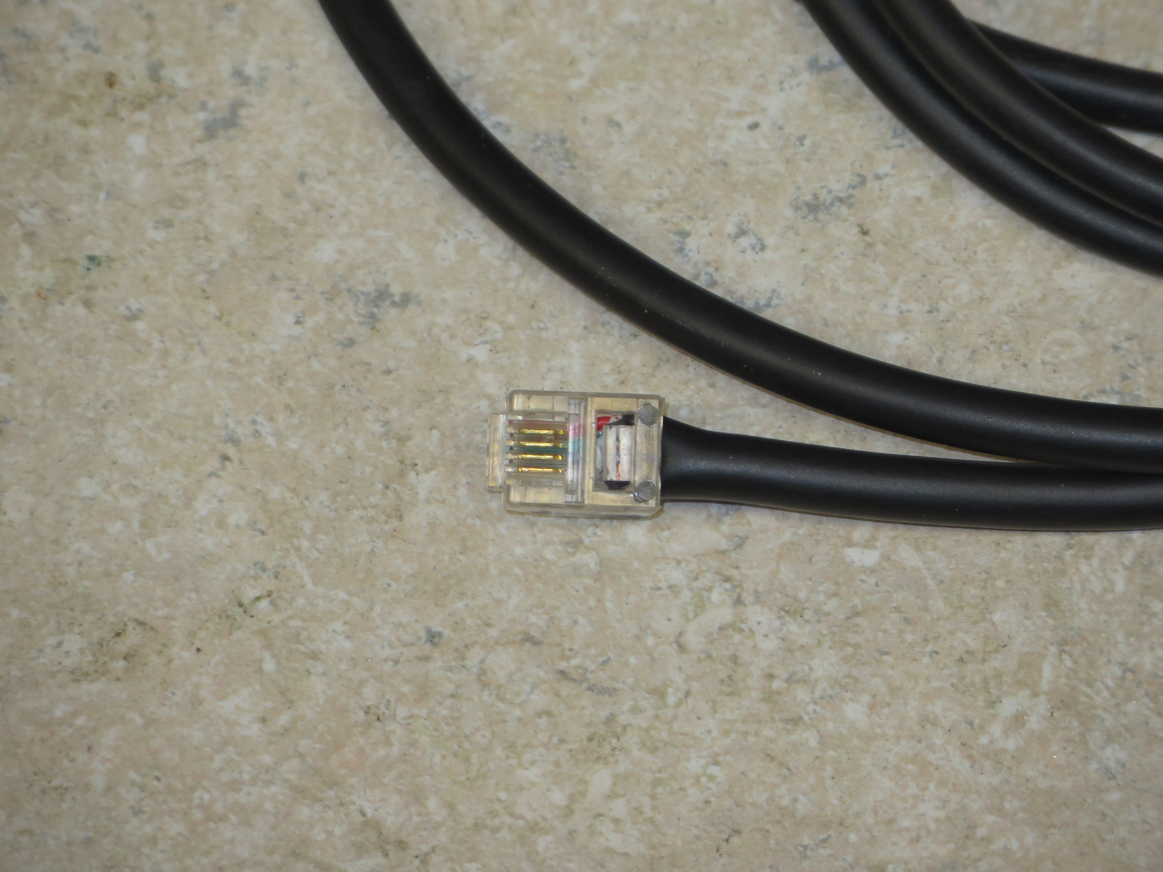
My solution was to purchase a 25′ male-male DIN cord from Amazon and cut it in half. I then stripped the ends and crimped on a 6p4c connector to the appropriate wires. It took a little doing to get the cable forced in far enough that the casing would engage with the strain relief, but it is possible.
At least for the cable I used, the pinout worked out as follows (your mileage may vary):
1 – no pin
2 – White
3 – Blue
4 – Green
5 – Red
6 – no pin


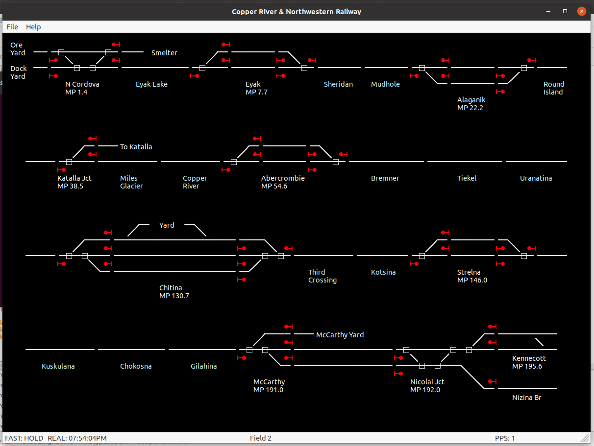
 on the bottom and the Chitina (third) Copper River crossing on the top.")


 and Mudhole will be in the back left corner.")


