Category Archives: Electrical

Posts related to wiring, signals, DCC, etc.

A Question of DCC

No, no, not the choice of DC or DCC.  That’s not a question around here.  There’s no way I could possibly hope to operate the CRNW on DC.  The real question is “what kind of DCC?”

I’ve been a Lenz guy for the last decade, and overall I like the fact it’s reliable, well-built, and works well.  Plus the throttles have a very solid, professionally-built feel to them.  That said, Lenz doesn’t offer a wireless throttle, and their products haven’t changed since I bought my system 10 years ago.   (CVP Products does offer wireless Lenz throttles that do work quite well, however.)  Wireless throttles are a must – there’s nothing I hate more than tripping over other operators trying to get to the next throttle jack.  On the up side, the system does everything I really need and – best of all – the throttle bus (XpressNet) is an open standard and fully documented.  This is a huge deal to me, as I tend to build a lot of my own hardware and I’m a rather big open source software and hardware proponent.  I don’t like being boxed in to any given vendor’s products, on the off chance they go out of business.  Because Lenz has an open, well-specified bus, I can pretty easily build my own wireless throttles.   if I wanted.

On the down side of sticking with Lenz is the facct they haven’t really done anything in the last ten years in the base station or throttle market.  Plus, their US market share has seemed – in my experience – to be slipping since Debbie Ames retired as their North American rep.   While, as I pointed out above, I could build my own throttles, I don’t really want to right now.  I have a layout that needs lots of work to get to operational, and I don’t want to get bogged down playing with electronics.

Having played with an NCE system at a layout open house several weeks ago and heard nothing but good things about them for years, I finally broke down today and ordered an NCE Power Pro radio starter set. My plan is to run the NCE system for at least the first phase of the CRNW’s life.  If it works well, it’ll probably stay for a good number of years, or possibly for the life of the layout. Expect a “first impressions” look at it in a few weeks.

(BTW, if anybody’s looking, Brooklyn Locomotive Works has an incredible deal on both the wired and wireless versions right now.)  I also ordered a Cab06pr from MB Klein, since BLW doesn’t seem to have them.

I don’t plan to get rid of my Lenz system.  I still like it, and some day may get around to building compatible bits for it.  For that matter, part of me really wants to design/build my own DCC system based on MRBus, and I have no doubt I could do it.  But now, in the formative years of a new layout, doesn’t seem to be the right time to pursue such interests.

Lighting & Benchwork Update

Those of you who have been following along know that one of the core electronic pieces I’ve been working on for the CRNW is an LED lighting system tied into the fast clocks.  Over the run of an operating session, I want to transition from “dark” (really dim blue light) through the brilliant warm light of daybreak, the bright white of midday, and the through the golden hour and sunset back to dark.    The system will consist of the fast clocks – obviously – as well as a MRB-GIO to figure out color and intensity, and then a set of power booster boards that actually control the 2000W going to the LED strips.  The power boosters will be local, each controlling <20ft of layout, to keep the amount of power being switched to a more manageable level.

The prototype power booster boards for the LED lights showed up a couple weeks back, but this weekend was really the first chance I’ve had to try integrating them with the full system.  I connected one up to my test LED strip and mounted it back over Cordova, and then connected it to a MRB-GIO and did some basic programming to turn it into a lightning controller.

Results are promising – I need to do a bunch more tweaking on the exact light transitions, but my first try came off pretty well.  I also did a few tests using a bunch more strips to increase load.  The system was designed for up to 6A per channel, so I cranked it up to around that.  Heating was actually less than I expected – the board only slightly warm to the touch even switching 6A on a couple channels.

I’ve posted a few photos of the new power control board, as well as some samples of midday, evening, and night light.  Night isn’t that bright, I promise.  It’s just the camera evened out the exposure.

On the benchwork front, I did get the top deck extended from Strelna over to the north end of the Chitina yard.  The bottom deck is still being pondered – I’d really like to add a short Katalla Branch as a very low level.  The problem is that I can’t figure a way to shove a helix under where the junction should be.  I’m contemplating a train elevator along the wall (hidden behind the Miles Glacier Bridge area), since trains to/from the coal fields above Katalla would be short – 6-8 cars plus power.  Regardless, I’m still pondering it.

Oh well, off to Memphis for the week tomorrow.  I’ll figure out what I’m doing about a potential Katalla branch train elevator when I get back.

CRNW LED Lighting, Round 3

Honestly I got almost nothing done this weekend in terms of benchwork.  Nearly all of my efforts went into other, non-model railroad tasks and then into working on the LED lighting system a bit more.  I’m running another set of boards soon, and wanted to get enough groundwork done to get the LED driver boards into this batch.

Tasks left to accomplish were as follows:

  1. Work out mounting to layout and characterize thermal/electrical parameters in operation
  2. Solve the inductive ringing problem in the LED drive
  3. Plan how lighting control would be distributed and design power control board

Task 1:  Mounting Considerations for LED Lighting

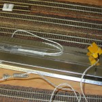
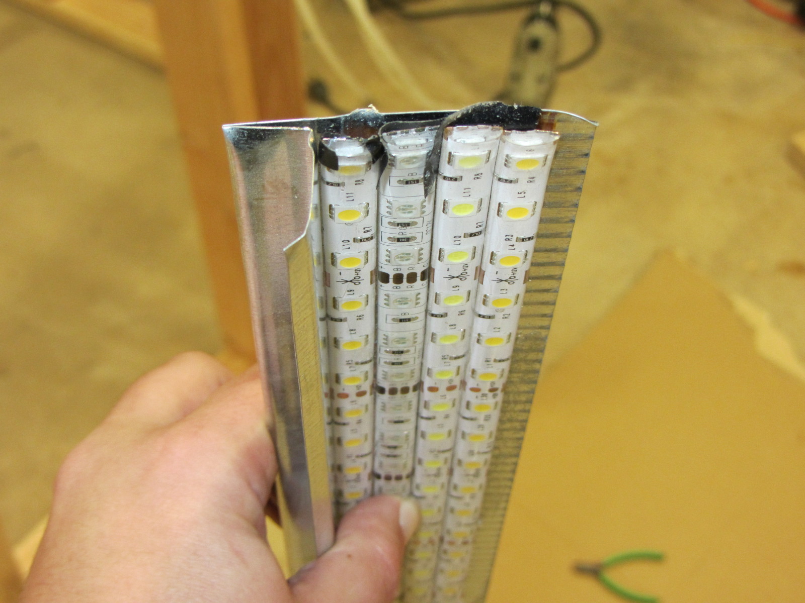
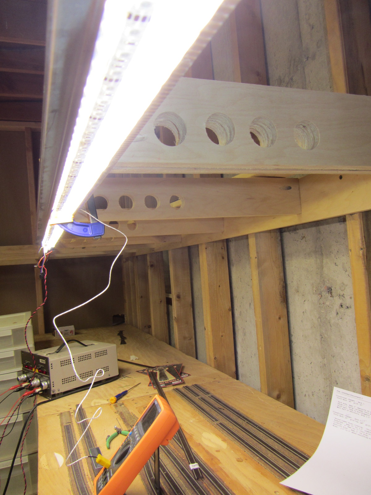
Some time back, roughly when I started benchwork construction, I found some great T-shaped galvanized steel drip edge (intended for roofing) at Lowes.  Strong due to its folded shape, light, wouldn’t rust, metal (to provide some heatsinking and protection between a potential high current short and the wooden benchwork), and cheap ($~4 for a 10 foot strip when I bought it), it seemed the ideal material.  Plus, the folded edge would reflect light back towards the layout and away from the aisles.  I put a single strip in with one of my lumber purchases, and it’s been sitting in my garage for the last four months.

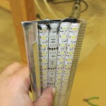
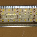
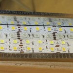
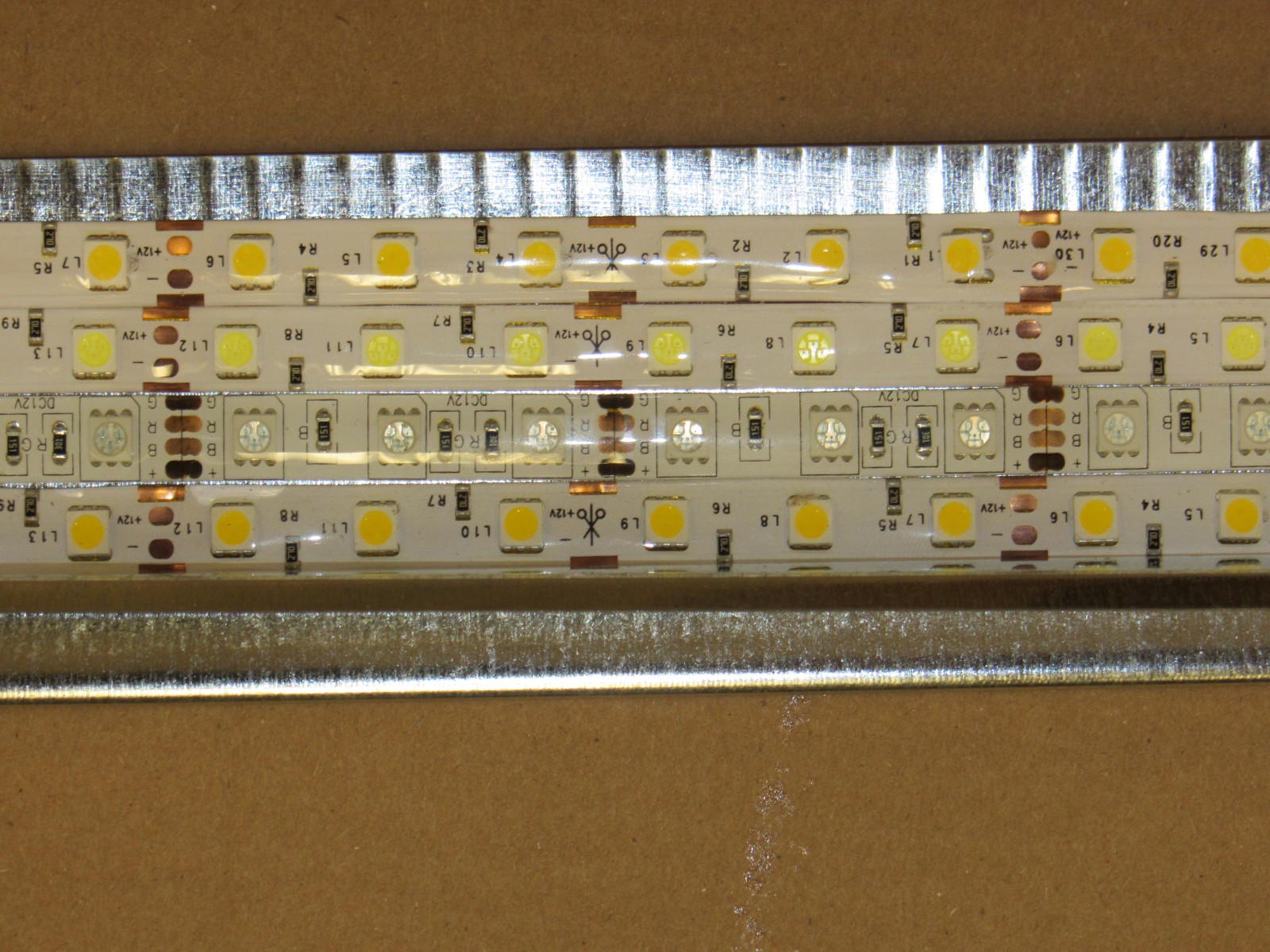
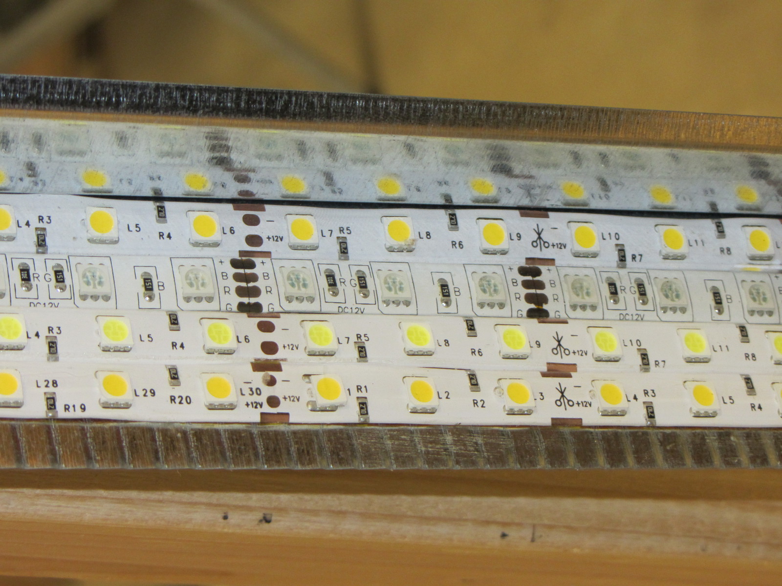
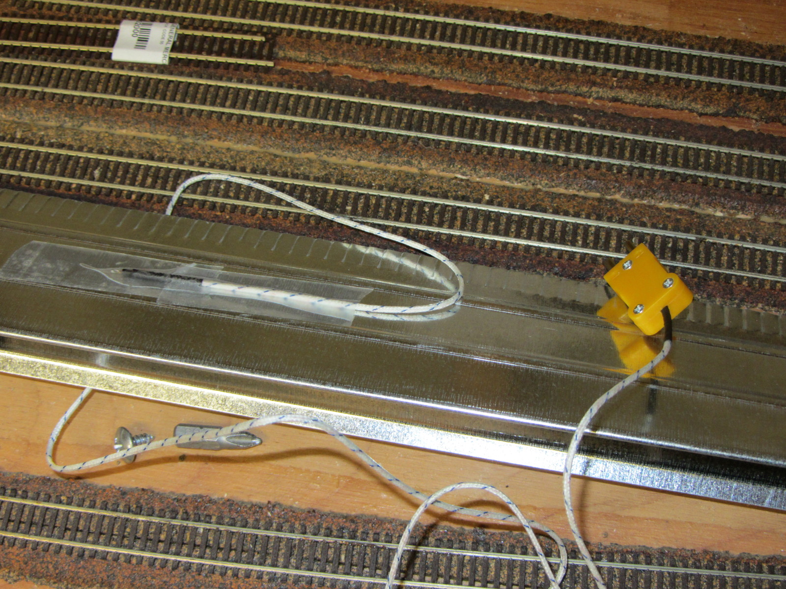
Today, I cut off a four foot section of the stuff, since that matched the LED strips on my test piece.  Using a thorough coating of Loctite 300 heavy-duty spray adhesive (I’d previously tried my usual go-to adhesive – 3M 77 – and was underwhelmed), I laid out the four planned LED strips on the steel -warm white #1, RGB, cool white, and finally warm white #2.   Each strip was harvested from the original test 2×3 board, so these have been used a number of times now…

An end view, including the electrical tape used to insulate the exposed ends A look straight down The four strips - warm white, RGB, cool white, and warm white 2

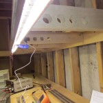
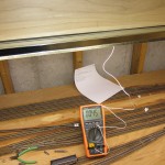
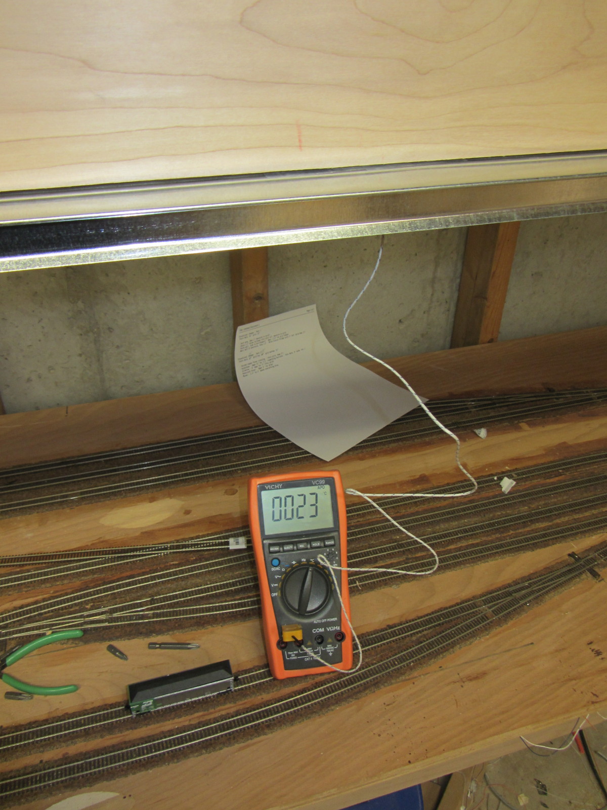
With the strip prepared, I then mounted a thermocouple to the top of the steel to monitor the temperature.  Using a bar clamp, I attached it to the layout (in the usual test position, over what will become the Cordova yard someday) and powered it up with an old bench supply.  Ambient temperature at this point was about 23C (73F). Current was approximately 3A for 3x 4′ strips of white being lit simultaneously.

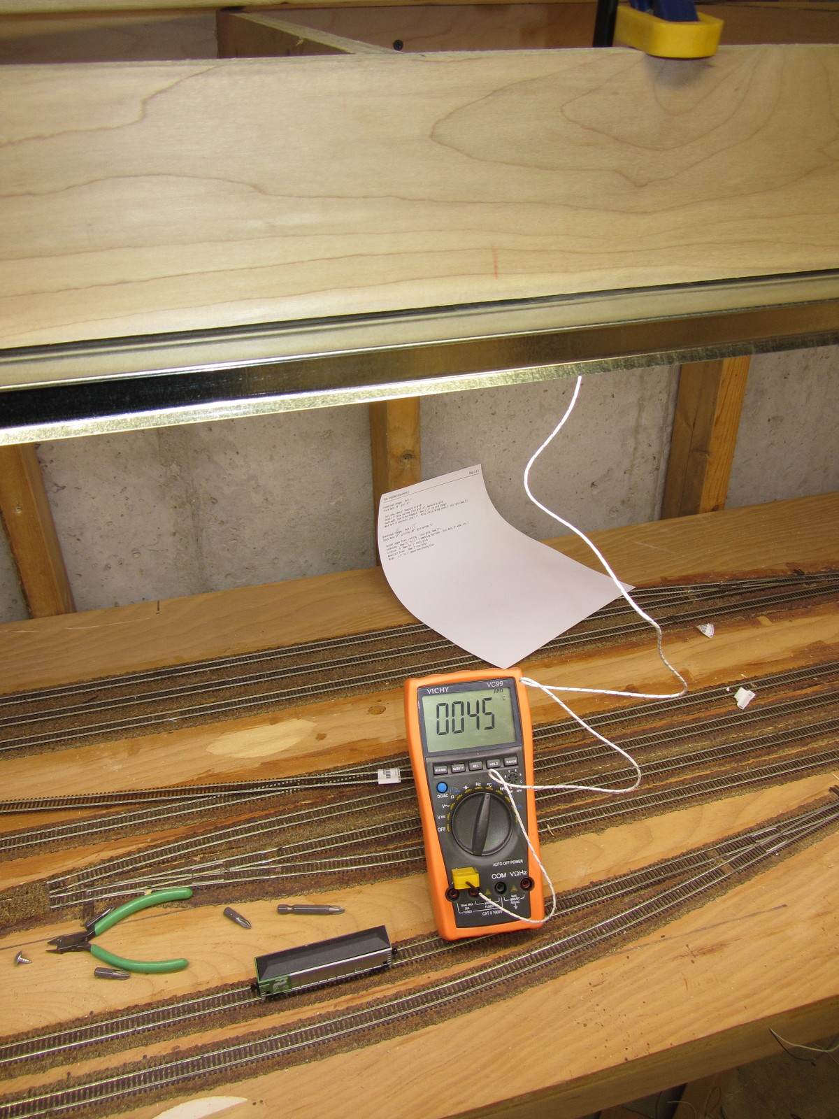
I left the lights alone for an hour as I did other things, so that I could see where the temperature would stabilize.  Turns out, the answer is at approximately 45C (113F).  The steel was warm to the touch, but the strips were notably cooler after an hour of running then when they were mounted to a piece of wood.  It looks like the heatsinking works!  LED longevity is closely linked with temperature, and once you pass an operating temperature of 50C, things start going downhill in a hurry.  45C for three strips running at 100% (more than I plan to run in actual operating conditions – my plan is currently at most 2 at 100%) is pretty darn good.

The temporary LED strip mounted up on the benchwork with a clamp.The thermocouple on the back of the steel mounting plate.Initial temperature - 23C Final stable temperature - 45C

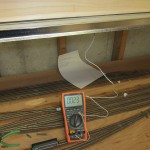
One interesting note – the operating current at 45C had increased to 3.3A.  This makes sense – bandgap of LEDs decreases with increasing temperature.  So, with less voltage drop across the LEDs, the ballasting resistors (56 ohms total, split into two 1206 resistors – see more about this later) allow more current.  So, as a note, LED strip lights appear to have a 10% current rise over the 20C between room temperature and operating temperature.  Almost all of that additional power will be dissipated in the resistors, so it’s not even going into providing useful light.  (See analysis in the final section.)

Task 2:  Fix the Inductive Ringing

The drain side of the FET with an undamped load
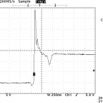
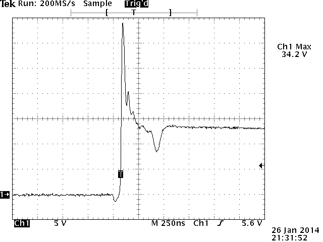
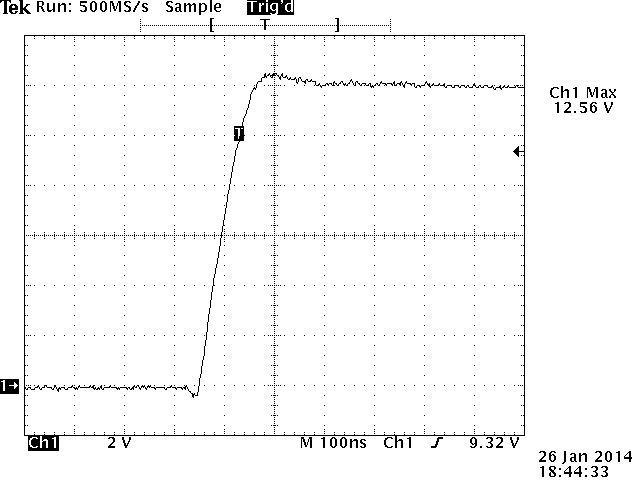
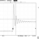
When I initially investigated doing variable LED control for layout lighting, I noticed some reasonably nasty inductive spikes whenever the MOSFETs controlling the strips would shut off. The screen capture from my scope on the right is a pretty typical kick – the FET shuts off, and the drain side of the FET would ring up up obnoxiously high voltages.

Since I’m only planning on using FETs with a 30-40Vds rating, these spikes could easily turn into circuit-killers.  Plus, they’re likely radiating lots of electromagnetic noise that will cause other issues down the line when I have 100+ amps of LED strip lights running and switching on and off.

2.5A with a FR155 diode
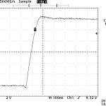
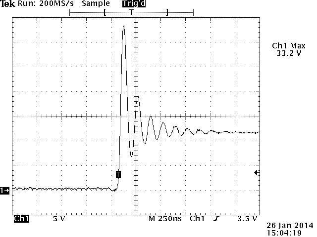
My initial hope was that a freewheeling diode from the drain up to the+12V rail would solve my problems.  I was operating under the assumption that my problem here was inductance in the LED lines, and that if I gave the current somewhere to go, my problem would go away.  At low currents, it looked promising, but as I started pushing 2-3A through my test setup, I got the waveform on the left.  Better (less ringing), but still with the 30+V spike before the diode got going.  All I had on hand for reasonably quick diodes were some old FR155s.  While great at reverse recovery time, I can’t find a spec on how fast they go into forward conduction.  Regardless, a decent Schottky diode should beat them hands down.  I just don’t have one to try.

22nF damped from drain-sourceAn alternate approach I tried was to damp the system by applying a small capacitor between the FET’s drain and source.  As little as 22nF was enough to significantly clean up the waveform, and 0.1uF damped it out completely.  I don’t like the idea of a capacitor in there, though, because this will almost certainly need to be quasi-matched to the parasitic inductance in the lights.  I’m going to try a faster diode first and see if that fixes my problem.  If that doesn’t work, however, we’re back to some sort of RC snubber circuit.

Task 3: Plan a Lighting Control Scheme

Safety in designing this light system is paramount.  Given that the layout will consume at most ~150A of current to run the lighting (at 12V, but 150A is still a lot of I2R heat in any short or questionable connection), fuses in all the right places are a key design feature so that any failure doesn’t end catastrophically.

Per measurements taken at steady-state in the test fixture, any of the white strips are going to take 0.275A/ft at 45C.  The RGB strip will need approximately 0.1A/ft for each of the three channels lit.  So, figuring on an absolute maximum of three full strips (all three whites) on at any given time, I’m looking at 0.825A/ft maximum.

My initial plan had been to use larger modules, controlling as much as 30A through a single control board.  However, that means larger FETs, larger freewheeling diodes and snubbers, and larger wires everywhere, since any potential short may have to soak up 30A @ 12V until the fuse goes.  Given our 0.825A/ft metric, a 30A module would feed ~35 feet of layout lighting.  The heavy wire that I would need to handle any possible shorts over such lengths quickly showed this as an impractical approach.

If I used the 10ft length that the steel flashing comes in as a module length instead, that’s 8.25A per module, maximum.  That’s nicely under a 10A fuse by a decent safety margin, and most wiring that I would use could handle 10A for a short overload period until the fuse went out.  (Mini-ATO blade fuses like I’m considering using will blow in <0.75s at 135% of their rating.  So 13A would take it out in less than a second.)

My current plan is modules for every 10ft section, with one single input fuse of 10A.  Each board will then have 6 N-channel FETs (likely 3x AO4882 duals), 6 FET drivers (likely MCP1416s), and six optocouplers, along with dual RJ45s for the control bus (one in, one out).   A single Cat5 cable will run around the layout, delivering signal ground and 6 light PWM channels from a main lighting control board to the optoisolated inputs on each booster node.

I have the schematic done, but it’s already pushing 2300h and I’m tired.  Have to go to that real job tomorrow, so I should probably get some sleep and put the board off for another day.

Addendum:  LED Strip Lights and Voltage

As sort of an interesting side research project, I decided to investigate more about the relationships in LED strip lighting between input voltage, power dissipated in the two ballasting resistors, and power actually delivered to the LED lamps themselves.  Some of my discussions earlier in the day with a friend had made me wonder what the relationship really was between these three things.

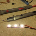
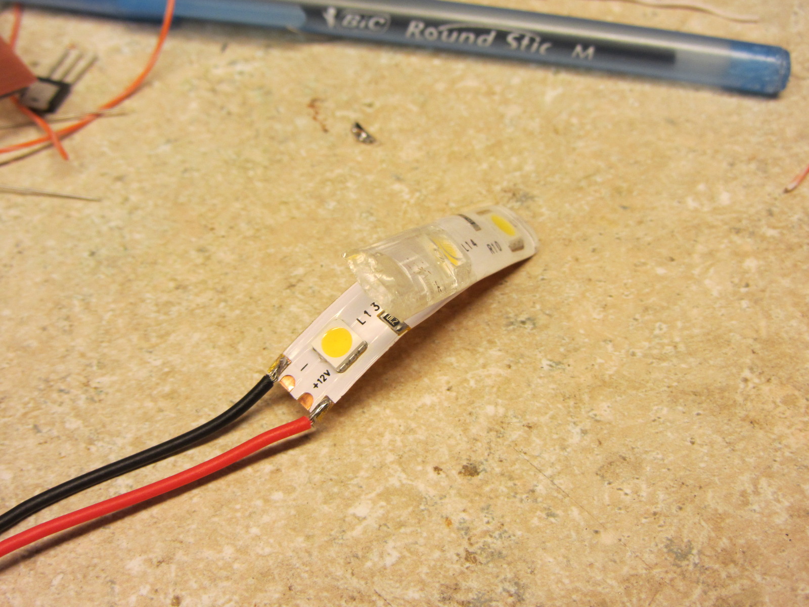
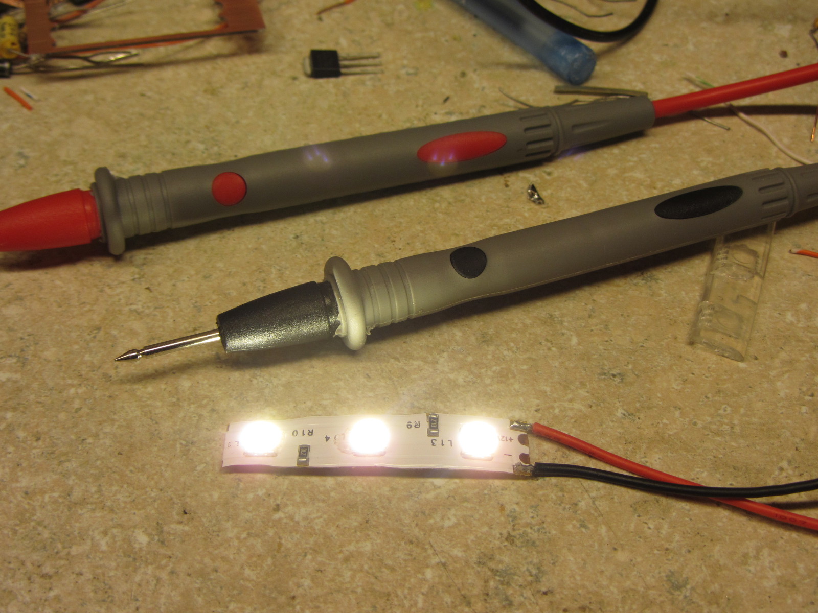
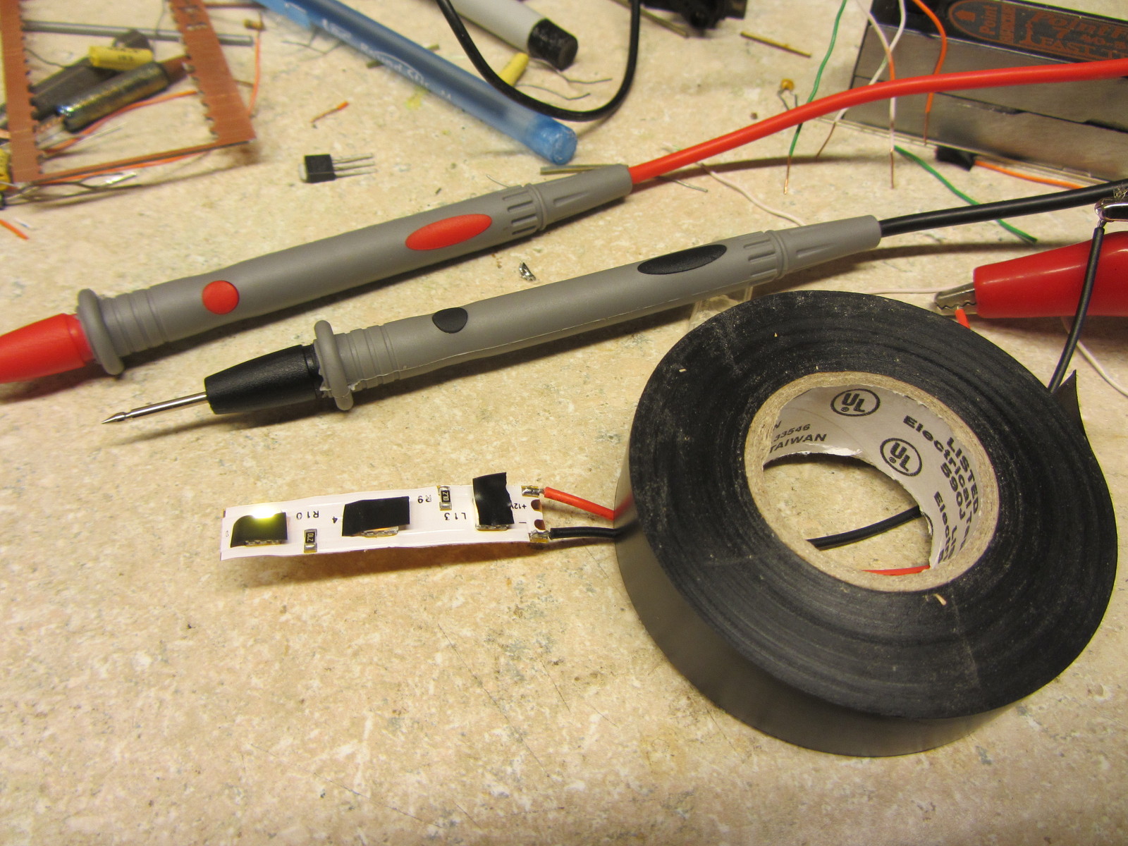
Step one was to just cut off a piece and decapsulate it so that I could get probes right on the pins.  Not really that hard – with a little encouragement, the coating peeled right off.  I then powered it up and realized that having three death rays shining in my eyes as I was trying to probe was going to be a real problem.  So, I used a trick I learned long ago when dealing with warning lights on cars that shouldn’t be on but inexplicably were: grab the electrical tape and – poof – no more annoying light!

led-strip-decapsulate led-strip-owmyeyes led-strip-better

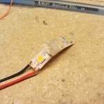
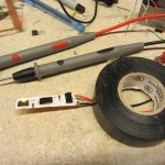
Internal construction of these strips (nominally rated 12V) consists of a 27 ohm, 1206-package resistor (rated for 0.25W of dissipation) between +V and the first LED, then three LEDs in series (each “LED” being a 5050 package with three LED die inside in parallel), and then another 27 ohm resistor to ground.

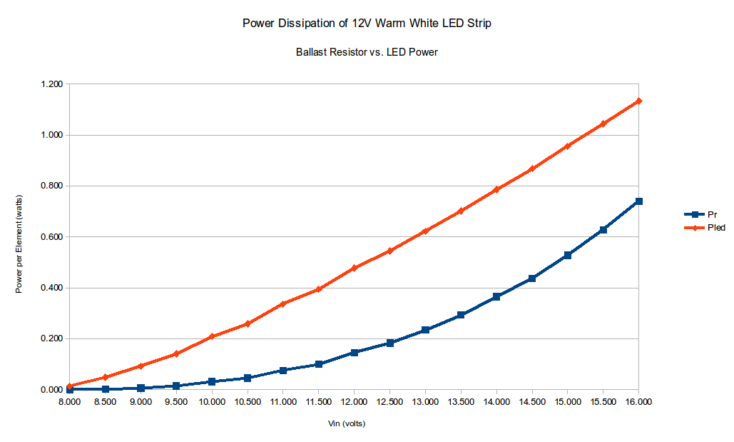
Procedurally, it was just a matter of punching each voltage into the power supply, measuring the voltage across one of the resistors, and plugging the result into a spreadsheet.  Given the input voltage and voltage across one resistor, I could calculate the current through the circuit, and thus the drop in both resistors and consequently the power that must be dissipated in the LEDs themselves.

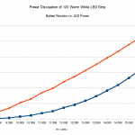
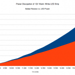
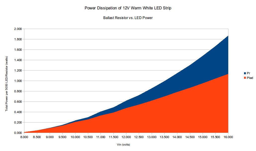
Here’s a pair of graphs of the results.  The first is just power burned in each type of component – blue being resistors and orange being LEDs.  In the second graph I stacked them, so that you can see how large of a percentage of the total is burned off as unproductive ballast resistor losses at high voltages.

Power dissipated in the resistors vs. the LEDs for various input voltages A stacked graph of resistor/LED power, to give you a better idea of their relationship as part of the total draw

It really makes me wish for a constant-current design, but I realize the additional complexity that would entail.  Cheap constant-voltage LED strip is cheap – custom engineering my own is expensive.  Darn.

Happy New Year!

Like any good model railroader, I spent New Years Day in the basement working on the layout.  I was hoping my Fast Tracks jig would arrive on New Years Eve, but alas, it did not.  So, I reverted to working on lighting, benchwork, and some electronics design.

The good news is that the entire layout room now has proper room lights – nine fluorescent 4′ dual T8 fixtures, to be exact.  It makes it much less of a dingy hole in the ground and much more a presentable layout room.  Now if only the construction disaster would clean itself up…

As far as benchwork, I accomplished a piddly 32″ – the upper deck between McCarthy and the Kennicott River crossing.  The electrical took longer than expected, and I needed to accomplish some design work  for Iowa Scaled for a new optical track detector we’re working on.

My goal for the rest of the week is the rest of the east wall (McCarthy to Kuskulana on the upper and Cordova to Eyak on the lower) and – if the stars align – the rest of the wall framing and clean up some of the random junk in the way of progress.  We’ll see what actually happens.

CRNW LED Lighting, Round 2

While I was in Indianapolis, I received a call from DHL…  They had a box from China, and I hadn’t been home for the first two delivery attempts.  Woohoo!  The LEDs for lighting the layout arrived (all 500 feet of warm white and 250 feet of cool white) early!

When I arrived back in Colorado (which turned out to be a long and annoying tale on its own – thanks a lot, United…), the other piece of the puzzle was in the mail – an RGB LED strip.  As you’ll recall, my plan was to combine two warm whites, a cool white, and an RGB strip, so that I can vary both the intensity and color of layout light.  Eventually, I plan to integrate that with the fast clock system so that over the course of an operating session, the light will change to model the real change in daylight.

While I want to get going on benchwork again this weekend, I couldn’t go get more lumber because it’s (quite unusually) pouring rain outside and I loaned my truck to a friend.  So, given that I had some power MOSFETs and a MRB-GIO sitting around, I decided to try building a prototype MRBus light controller.  Turns out it was pretty darn easy, aside from some thinking about correct snubbing on the FETs to prevent inductive kick from killing them.  I’ll post a schematic soon, but for now, I’ll show some pictures of the prototype.

In the pictures, you’ll see the MRB-GIO, the breadboard with the power drivers and snubbers, my trusty Lambda power suppy, and then the test LED strip, showing all the different ways it can be turned on and dimmed.  Then there’s also a couple photos of some early tests – I could just send intensities over MRBus to the controller, and lights would change.

This is going to work beautifully…

LED Lighting Rethought

So last night, as I was trying out various LED strip configurations, I was trying to match my old fluorescent tubes in terms of illumination without regard to overall power consumption, cost, or anything else.

Today, sitting at work, reality smacked me upside the head.  Each deck has approximately 110 feet of linear run, so 220 feet of lighting for the whole layout.  Assuming four strips of LEDs going strong for main lighting, that works out to 4.8A/4ft, or ~1.2A per foot.  That’s 264 AMPS of 12 volt power, or 3.2kW.  Yikes!  Given at a 20A house circuit can only source 2.4kW under ideal conditions, that’s probably 2-3 house circuits just to light the layout. (Remember, any power supply isn’t going to be 100% efficient.  In fact, 75% would probably be a good day.  Then, unless it’s power factor corrected, that’s going to get even worse.)  Given that my breaker box is buried in a finished wall, running new circuits would be painful.

After some tinkering when I got home, I came to the conclusion that two LED strips is probably “good enough”.  That’s only 1.6kW, which even assuming crappy power supplies should easily fit on existing circuits I can tap from the basement.  So, I ordered enough LED strip to complete the layout this afternoon…

Now off to continuing to demolish the old layout and clean out the basement for new construction.

CRNW LED Lighting

My old Canadian Arctic Railway layout was planned to use dual 4′ T8 fluorescent fixtures mounted above each level.  I’d never been particularly happy with that solution, since even the decent-quality electronic ballasts would buzz slightly, and the fixtures were completely un-dimmable.  Plus, I always had some residual concerns about UV light from the bulbs damaging scenery.

I’ve been convinced for some time that LED strip lights were the way of the future.  Small, silent, efficient, easily controlled (they’re only 12 volts!), and available in a wide variety of colors, strip lighting seems to promise massive improvements over under-layout fluorescent fixtures.  The downside is the need for very large 12V power supplies and – until recently – the pure cost of it.  Fortunately, with recent advances in LEDs and direct access to Chinese vendors via eBay and Alibaba, those two concerns have largely gone away.

In addition, the infinite dimmability of LEDs and the variety of available colors opened up the possibility of something I’ve wanted to try for a long time – modeling the day/night cycle!  The basic idea would be to have the layout lighting adjust the intensity and color blend based on the fast clocks, so that as the day progresses, dawn grows into mid-day, which fades to afternoon and the “golden hour”, which gives way to the “blue hour” and then eventually night.  With the right mix of colors and some simple power controllers attached to the MRBus layout network, such a thing should be relatively simple.

I ordered three 5 meter spools of 5050 (5.0mm by 5.0mm component) LED strips from China via eBay (my secret source…): one warm white (3200K), one cool white (6500K), and one blue.  After two weeks of waiting on the proverbial slow boat from China, they arrived this afternoon.  I wasted no time getting them downstairs, finding a suitable 4 ft. board (same as the fluorescent fixture), and cutting off strips to test.

I finally settled on 3 warm white and 1 cool white strip, when lit together at 12V, gave me similar lighting to the old tubes.  One cool white and one blue strip, lit at about 10% power, gave me a reasonable “night”.  No, it’s not as dark as a real night, but it’s a decent approximation for my operators.

No mix I could find, however, gave me a suitable sunrise or sunset color, so I’ve ordered another strip of 5050 RGB LEDs.  I’m hoping that by using the warm and cool white strips as the “bulk” light, and then “flavoring” it slightly with color from the RGB strip, I can get satisfactory colors for all times of day.  More to come once those LEDs get here…

I’ve included pictures of this evening’s test below.

Also, as a teaser, the first part of my CR&NW’s roster showed up today…  Meet the 600s, a set of 6 SD60M three-window units that will eventually be numbered 600-605.  (Yes, there’s a spare shell there, just in case I’m not as good with the ol’ airbrush as I used to be.)  Obviously with the real CRNW calling it quits in 1938, they never had diesels.  However, as I’ve mentioned, mine will be set in the present day.  In my world, the SD60Ms showed up on the property in 1990 to replace the aging fleet of SD9s that had originally replaced steam in the 1950s.  But more on my fictional modern day roster another day…