Category Archives: Uncategorized

Auxiliary Power Converters

Like most layouts, the CRNW will need a variety of voltages scattered about for turnouts, signals, structure and scenery lights, etc. I’ve seen various solutions to this problem over the years, ranging from a single auxiliary power bus with local regulation, to multiple aux power buses running at different voltages, to the worst of all possible options (which I’ve seen on more than a few layouts): various old power packs, wall warts, batteries, scattered all over the place to power everything.

Myself, I’m a single aux power bus sort of guy, with point-of-load regulators to deliver whatever voltage is needed. That way, I can delivery 8-9V for MRBus and MRServos, 3V for structure lights, 12V for local NCE cab bus power injection, etc. and only have to run one large, high power bus around the layout to feed everything.  My traditional preference is to run the aux bus at a nice 24VDC.  That means using linear regulators for local voltage generation is pretty much out, as you’d burn a huge amount of power in the regulators.  As an example, take the Nizina Yard and its two MRServo-2s.  They’ll need ~8VDC, and will each draw ~50mA just sitting there if the relays are on (as they’ll be for one direction or the other).  That means the two turnout motors will be drawing 0.8W (8V * (0.05A * 2)), but the regulator needed to create the 8V will be burning 1.6W ( (24V – 8V) * (0.05A * 2) ).  That means that my point-of-load regulator is only 33% efficient.  And it only gets worse from there.

The answer to this is something called a switching regulator (aka a switchmode power supply or simply “switcher”).  Basically, rather than burning off the excess electrical power as heat, switching regulators convert that excess to a magnetic field.  For some small amount of time, they’re switched on, powering the load and storing excess energy in building the magnetic field.  Then they switch the input off and power the load by collapsing the magnetic field.  If you change the ratio between the on and off times and do it very quickly, you get very good regulation and a large percentage of the power actually gets delivered to the load.  It’s not uncommon for switching regulators to be 90+% efficient, which is why they’re becoming common everywhere.

The problem with switchers is that they’re much more complicated than linear regulators, and thus typically more costly.  Fortunately, Chinese manufacturers do things on scales that boggle the mind and do it with parts that are sometimes of questionable heritage, driving costs to an insane minimum.  Popular on eBay are switching converters based on fake National Semiconductor (now Texas Instruments) LM2596 parts.  Often available for around $1 in small quantities, these are a full, adjustable output switching converter on a small PCB, including the control chip, inductor, input and output capacitors, diode, and a potentiometer to set the voltage.

Typical eBay fake LM2596 module

Typical eBay fake LM2596 module

However, now’s an appropriate time for a disclaimer.  One of my favorite quotes from a movie character is from Burt Gummer (played by fellow model railroader and actor Michael Gross):  “The possibilities for disaster boggle the mind…”  At the prices offered for these boards, the LM2596 parts used are almost unconditionally fake, Chinese cloned parts, thrown together into a module where every corner has been cut and every substandard part has been used to minimize costs.  As such, it doesn’t behave like a real quality National/TI part, specifically when you start pushing the limits with regards to current and temperature.  Specifically, if they get too hot, they don’t shut down like a real one.  They just short, sending full input voltage to the load.  If your load can’t handle it, it goes up in smoke.   However, I’ve used a lot of them on various model railroad applications over the years, and as long as you use them conservatively (meaning don’t do more than 1A continuously), they do work and work well for $1.

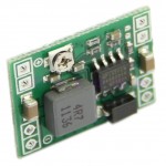
eBay MP1584EN module

eBay MP1584EN module

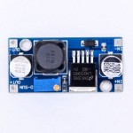
A new module started appearing on eBay a couple months ago – a much smaller design, based on (theoretically) a much more modern switching chip.  The chip appears to be an MP1584EN from Monolithic Power Systems, and the board is about the size of a quarter.  Again, they’re available for about $1, which makes no sense at all, given that real MP1584EN parts are over $1 even in 10,000 unit quantities, and that doesn’t take into account the other parts, the board, or putting it all together.  Either the Chinese got a hell of a steal on their parts, or once again we’re dealing with a cloned part.  So what did I do?  Order a dozen of them for evaluation, of course!

In the usual 2-3 weeks, a bag showed up in the mailbox with a whole bunch of the little modules in it, each individually packaged in an ESD protection back.  Each module is about the size of a US quarter – exactly what the dimensions on the original eBay listing promised.  However, the holes are not exactly where they were specified to be – the upper and lower groups are 30 mils too far apart and the right and left groups are also 30 mils too far apart.  Otherwise, they’re pretty unremarkable.  So, the next step was to solder up wires and beat them up electrically to see if they’d survive layout use.

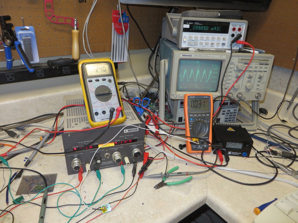
The test setup involved a bench supply pushing 24V, meters for input voltage and current, a meter for measuring IC temperature on the switching board, and then a programmable current load (the Re:load Pro from Arachnid Labs – a remarkable piece of gear for the pricetag) for actually sinking the power.  Oh, and we’ll throw my scope on the output to check for ripple as well.  What you wind up in terms of bench litter looks something like this:

The test setup on my bench

The test setup on my bench

The first one was dead, straight out of the ESD bag.  It had quiescent current draw (200uA or so) but no output.  Didn’t matter if I twiddled with the pot or anything, it was just pain dead.  I suspect the IC itself had a bad power switch, as I couldn’t see any voltage on the output to feed the inductor.  Well, write that one off as a mechanical sample only…

The second one fired right up and did exactly what it was supposed to.  For the simulation, I chose 24V as the input voltage, matching my planned accessory bus, and 8.5V as the output voltage since that’s usually what I feed to MRServos and to the MRBus network.  At each current step, I’d set it and go do other things for five minutes to allow the temperature to reach steady state.  (The room was approximately 68F / 20C during the testing.)

Here’s the raw data:

Target Current Vin (volts) Iin (amps) Vout (volts) Iout (amps) Tsteady (deg C) Vripple (mV rms) Eff (%)
0.25A 24 0.1 8.47 0.249 31 11.9 87.9
0.50A 24.1 0.196 8.45 0.499 35 15.8 89.3
0.75A 23.8 0.296 8.43 0.75 41 16.1 89.7
1.00A 23.5 0.398 8.41 1 47 16.6 89.9
1.50A 23.9 0.588 8.37 1.5 53 18.2 89.3
2.00A 23.2 0.817 8.31 1.99 69 20.1 87.2

At 2A, the part was right on the edge of thermal limiting.  It would cut out for a few fractions of a seconds every 5-10 seconds.  Above 2A, it was in thermal limiting more than it was out.  So realistically, running these at 1.5A would seem to be a safe maximum.   Efficiency is also decent – ranging between 87-90% for my test cases.  Not bad for a $1 converter board.

On the other hand, the testing proved that thermal limiting does indeed appear to work.  Additionally, I subjected the part to repeated short circuits on the output with no apparent harm.  It gives me some faith that if this is a cloned control IC or at least one that failed some part of QA (and I have every reason to believe it would be, as discussed earlier), that these actually will function well enough to meet my needs.

Because these boards won’t be very handy to work with directly, and I have a rule that any switching converter hanging off the high current auxiliary bus have a fuse (since a tiny board like this suddenly dissipating 200W+ (10A@24V, my fused limit back at the power supply) seems really bad), I’ve designed a carrier board for them that includes an input filter cap, a ATO-style fuse holder, terminal blocks for the input and output, and a “power on” LED.  Pretty simple board, really, but should make working with these things a lot easier.  It’s off to fab right now, but I should have it back by Christmas and can report on it as well.
What Day, What Year, What Season?

For many prototype and proto-freelance modellers, their layout is set in a specific month of a specific year, or perhaps even a specific day.  There’s absolutely nothing wrong with that, but I’m not that guy.  The CR&NW will take more of the approach that Eric Brooman took with his Utah Belt – time on the layout marches forward with reality.    Given that the basic reason for the line’s existence – copper ore hauling – won’t change substantially year-over-year, neither will my dedicated freight car fleet or motive power.  It does, however, allow me to adjust the interchange traffic and an occasional lease unit that will show up online, and vary the mix a little bit.  Rather than being in perfect lock-step with real time, I do think I’ll set it about three years in the past.  So, for example, 2014 in real life will be 2011 on the layout.  That allows me as an otherwise busy modeller time to ponder how the railroad would respond to real life FRA mandates, economic conditions, etc., and adjust things accordingly.

The one catch is that it will always be mid-September on my Copper River.  That’s because for years, it seemed as if I was always in Alaska in late August or September.  Alaska to me was always in the fall, and just jumped forward a year at a time between visits.  I love the colors of the trees that time of year, and the light is beautiful.  The rivers will still be running with a fair flow, but not raging full of sediment and debris and looking for all the world like a torrent of liquid concrete.  There’s no hint of snow yet at the elevations and regions modelled – only at worst maybe a heavy frost – though there may be some far up on the mountainsides.  The weather is still pleasant, but the menace of winter is looming.

I think how we’ll handle it is that we’ll start operating sessions in January with the model date being about September 7, and just let scale time march forward as it does.   I’m going to aim for getting a full 24-hour day in each op session, running the FC around 4:1, but I won’t know if that’s actually going to work out until I have a layout that can be operated and a few guys to try it out.  It may be that 4:1 is the right ratio, but we only run 12-18 scale hours at a time because everyone tires out after that.  In that case, we’ll just stop the clock when we get done and pick up from there at the next session.

It’s all very exciting to ponder, and quite frankly I really wish I could just snap my fingers and get all of the trackwork, scenery, and equipment ready to go, but there’s at least a year or two of work ahead of me before we’re even close.

Influences

If I had to list the two layouts and modellers that have influenced my concept of modelling more than any others, it would have to be Tony Koester’s Allegheny Midland and Eric Brooman’s Utah Belt.  One of these days I’ll add a post about the influence of the AM, as I really credit the two part Model Railroader article in Dec 1987 / Jan 1988 as what hooked me on the idea of an operations-oriented, proto-freelanced layout.  But for now, let’s concentrate on the Utah Belt.

Brooman’s beautiful Utah Belt was the first layout to put the idea in my head of a modern proto-freelanced railroad that moved forward with time.  The AM seemed to move forward or back in jumps whenever Tony would get the itch to adjust the era, whereas the Utah Belt moves forward relatively linearly.  New power shows up, aging power fades to local and helper service, and old power fades from the roster.  It’s all nicely consistent and feels like what a real road would be doing at that time.  Plus, the way Eric captures the deserts and mountains of the Four Corners region is quite spectacular.

I never thought I would have the chance to see the UB in person.  I was at the St. Louis Railroad Prototype Modelers meet several weeks back with Iowa Scaled Engineering (otherwise known as “company I founded to sell stuff I’m building for somebody’s layout anyway”), and was contemplating what to do Friday night.  It was about that moment I saw the layout tour line-up for the evening, and noticed the UB at the top.  This was clearly a must-do, and anything else could be cast aside.

As a note, this is (at least) the second incarnation of the UB.   The new one is only approximately 40’x22′ (the first one was considerably smaller, apparently), but you’d never know it from the photos you see of the layout.  The layout is set up such that it just feels far more vast, capturing the desolate country it models.  Plus, it also has a vast number of photo angles available that all capture very unique scenes.

I forgot my camera, so sadly all I had on me was my cell phone.  Still, I thought I’d share some of the less blurry images with you.

Mr. Brooman, if you happen to read this – I can’t thank you enough for opening your home and your layout to visitors.  It was an honor to visit and, without a doubt, the highlight of the trip for me.


Benchwork Done!

At 2208h today, Sunday, 17 Aug 2014, benchwork for the two track levels is officially complete.  Woo hoo!  The only major benchwork yet to go is the upper lighting valance deck over Chitina.  Right now it ends above the third Copper crossing.  Unfortunately, I have a great deal to do for my day job this week, so I’m not anticipating finishing that up.  However, next weekend is largely open, so I should be able to start on the helix and getting the first track down.

I’m not posting any pictures right now because – due to construction and moving things out of the way – my basement looks like the apocalypse struck.  Once I get things tidied back up, I’ll post pictures.

One Year In

Today marks the one year anniversary of my efforts.  It was July 30, 2014, that I officially registered copperriverrailway.com as an effort to document my progress towards bringing the CR&NW alive again in my basement.

That said, I’m behind schedule.  Shocking.

I do have good news, however.  The base benchwork is probably a day’s work away from being complete.  I had hoped to announce today that as of a year in, I’d finally finished it, but I had to go help a friend of mine with her networking issues last night.  So finishing the final framing went on the back burner.  Hopefully by the end of the weekend I can officially announce that benchwork is done and we’re on to roadbed and trackwork!

Weekend Update

There’s not really that much to add – it’s the last weekend before taxes are due here in the US, so I’ve spent much of my weekend working on paperwork.  Ugh.

I did get to the layout for a few hours today and managed to install the gridwork for the upper valance along the walls with Kennecott / McCarty / Cordova.  It’s identical to the track level gridwork except for the lack of crossmembers.  I’m only installing a crossmember every 4′.  The grid doesn’t have to support much weight, except for the light strips and their cables.

The one gotcha is that the grid will have to cross the two windows.  I don’t want to block them, as they serve as secondary exits from the basement in case of fire or other emergency.  So I think what I’ll do is stop the grid on either side, and just have a magnetically-attached front board over the window area.  As long as I make the wiring harness so it also separates easily, this will preserve the use of the windows in emergencies.

In the process of putting the grid together, I got fed up with some of the scrap plywood I had sitting around.  So I also cut out the subroadbed for the Eyak yard area.  That consumed most of the remains of the sheet and got it out of my way in the process.

Benchwork Update

Just a quick note to say that progress is finally being made again.

Last Thursday, I ripped two more sheets of 3/4″ plywood to replenish my dwindling supply of plywood dimensional lumber.  It’s really remarkable how quickly building benchwork grid goes through a supply of the stuff.

This weekend, I’ve spent significant type tackling building the benchwork itself.  The result is that the grid is now complete from Kennecott through Strelna on the upper deck, and Cordova through mid-Alaganik (where it turns the corner) on the lower deck.

One of the things of note is the large gap for the Kuskulana River bridge.  My layout includes four of the railroad’s most notable big bridges – Miles Glacier, Chitina (third crossing of the Copper), Kuskulana, and Gilahina.  Three of the four are selectively compressed, but the Kuskulana crossing will be done to scale.   That means 238 scale feet of depth from railhead to water, or about 18 inches.  Fortunately, the deep vertical part of the canyon is only about 170′ across at the water line, and about 190-200′ at the rim.   The larger bowl sort of depression of the valley is about about 775′ across, or just under 5 real feet in N scale.  The CRNW spanned the gap using 2x 150′ deck trusses (one on each side) and a 225′ deck truss over the main canyon.  Then there was another 250′ of trestlework to connect the steel bridges with the grade.

Here’s a couple pictures from when I visited back in 2009 that illustrate the main chasm and the bowl-shaped valley it cuts through:

And finally, here’s the piece of benchwork that will eventually support the model canyon – yes, it seriously impinges upon the bottom deck, but it’s the only place I do this, and it’s to make a significant visual element that everyone familiar with the line will recognize.

That’s all for now, folks.  Hopefully I’ll have the gridwork done in a couple more weeks and be on to sub-roadbed.  After that, we’re on to track!

Ever Seen a CR&NW Train Order?

While this site is largely about my fictionalized present day CR&NW in N scale, make no mistake – I have a great interest in the history of the real thing as well.  It’s just one of those railroads that really captures the imagination.  Because the line existed in such remote country, was essentially a company railroad, and existed for such a short time, I’ve never found many relics of the real thing.   In the last few weeks, however, I’ve managed to pick up some of that operating paper.

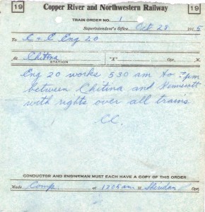
So, how many of you have ever seen an authentic CR&NW train order?  Well, here you go…  This one was written to engine 20 on October 28, 1915, allowing it to work between Chitina and Kennecott from 0530h to 1900h.  It’s absolutely amazing to me that a flimsy piece of train order paper from almost 100 years ago has survived to this day in spectacular condition.

crnw-trainorder

I’ve got a few more things from these finds as well – blank train order forms, agent’s ticket stubs, and a couple clearance forms.  Truly amazing stuff.  I’ll post the rest in the near future.

Cordova’s Docks

I’ve been working on a post about the alternate history that lead to my present-day version of the Copper River & Northwestern, and as part of that I was justifying the changes in Cordova.  I realized that my section talking about dock changes was getting so darn long and detailed that it might as well be broken out into its own post.

Specifically, one of the things I’ve contemplated since first imaging this railroad is, “How does the ore actually move out of Cordova, and in what form?”  The Good Friday Earthquake of 1964 provides some pretty good cover for whatever I chose to do – the quake caused land deformations and a moderate tsunami by the time it reached Cordova.  Contemporary news reports indicate that the docks were all but destroyed, and as such I’m assuming that if the CR&NW were still operating, it would have been required to rebuild its dock facilities.  As tragic as this event was in the real world, it’s like a get out of jail free card for the modeler.

Now, here’s the question – what sort of dock facilities would the railroad rebuild?  When the CR&NW was actually operating, the ore was so rich (or could easily be concentrated) to the point it could be economically shipped in sacks and pallets to the smelter in Seattle.  Eventually, Kennecott installed a concentrator to be able to process lower grade ore (but still insanely rich, by today’s standards).  Assuming the mines had survived, concentrators would have been increasingly necessary, as would using solvent extraction – electrowinning (aka SX-EW, basically dissolving copper and electrically plating it back out) to process the tailings and even lower grade ore.  There would have been no way to ship these low grade materials to the lower 48 economically for processing, so I have to assume increased processing would have been set up somewhere along the route – likely some concentration at the mine and some down the line, where there was more space, better access to power, and more hospitable weather conditions.  (Plus, it’s now in the middle of what’s now a national park.  I would hope that even in the 1960s and early 1970s before Wrangell-St. Elias was founded, there was enough sense to not bury such a unique and wild landscape in giant leach piles, but I’m probably hoping for too much on that one.)

How much copper and concentrate are we really talking about?  Let’s just go overboard for fun to see what the upper limits would be.   We’ll use a large open pit copper mine with a dedicated rail haul system – ASARCO’s Ray Mine  and Hayden concentrator-smelter complex in Arizona – as a sort of upper bound on what we might be dealing with.  The place is absolutely huge, but isn’t even in the top 10 as far as largest copper mines.  It cranks out 300+ millon pounds of copper from Hayden and 75+ million pounds of copper from SX-EW directly at Ray.  If you assume that’s all refined before it’s shipped, that’s only 187,500 tons, and at 100 tons/car and 365 days in a year, 5 railcars per day.  So let’s say that we only refine that to 50% concentrate before shipping.  It’s still only 10 railcars per day, or 1000 tons.

Looking through the various categories of oceangoing bulk vessels, we’d probably want something in the “Handysize” class if we were going to ship copper ore.  These range from 10000 to 35000 tons of DWT capacity.  So, assuming 50% concentrate, that means we’d have a vessel calling in Cordova roughly every 20-30 days to load up if we went with a bulk transport system. Not bad.  That’s a realistic call schedule for something running to the west coast of the lower 48.

However, this overlooks a few factors.  The US no longer has copper smelters anywhere on the west coast.  Currently, the only copper smelters operational in the US are ASARCO at Ray, AZ, Kennecott at Magna, UT, and Freeport McMoRan at Miami, AZ.  Canada only offers us one more – Xstrata’s smelter in Rouyn-Noranda, Quebec.  There’s nowhere for our bulker to offload to, except to transload onto rail again.   Also, I’m assuming that my “modern” Kennecott mine on the CR&NW wouldn’t produce anywhere near the output of Ray used in the example above.  Probably more like 200 tons of pure copper or 400 tons of 50% concentrate every day.  (That’s still 146 million pounds per year, which puts it in the middle of the pack for US copper mines.)   In addition, building a pure bulk loader doesn’t account for other inbound supplies that come by rail (mine supplies, fuel, etc.), outgoing non-ore freight (such as sulphuric acid from smelting, timber products, etc.), or even outgoing electrolytic copper from SX-EW processes.

Now our dry bulk freight isn’t looking so good.

The ARR has received car-float service from the west coast for years.  The ARR receives roughly one carfloat a week at Whittier, with a capacity of 50-ish cars per trip, plus the stacks of containers on top.  Certainly a surviving variant of the CRNW could do something similar.  So, given the ability to skip transloading, it seems like a rail barge slip would likely be the answer to the CRNW’s shipping problems.  50 cars per week is a bit tight, though, so we might have to have some extra capacity added on in the summer.

Besides, one ship a month sounds boring.  I’m a model railroader and this is my model railroad, after all, so I get to make some executive decisions about things that might not be the most economically plausible, but make my alternate reality a whole lot more interesting.  Having a removable rail barge that my operators have to load/unload in some prescribed order has a lot more potential challenge for my crews.  Otherwise, it’s just run the ore transport trains through a loadout loop and head back to the concentrator.  Again – boring…

That’s not to say the docks would have vanished entirely.  Cordova still today has a thriving fishing industry, and I presume the canneries would have also rebuilt in short order after the quake.  Rail service along the cannery dock would have provided them with incoming materials along with the ability to ship our refrigerated cars full of frozen fish.  (For perspective, Trident Seafoods lists their Cordova cannery as capable of processing 1.8 million pounds of salmon… daily!  That’s 900 tons of fish.  Even assuming only 10% of that is frozen, that could still be 1-2 reefers or 2-3 refrigerated containers a day!  Fresh would still need to ship via air freight, as a rail barge would need 5-6 days to reach the west coast terminals.)  So in my Cordova, there will be a wooden wharf area with a built-in siding, next to the barge slip.  Running frozen fish in reefers to distribution points in the lower 48 sounds like a reasonable proposition, or at least gives me some more operational possibilities.

So, that’s my rationale behind only providing Cordova with a 4 track barge slip and no bulk loader.  Bear in mind that I do air freight for a living, so my grasp on oceangoing bulk transport may be missing some key points.  If anybody who reads this has actual experience in these industries, I’d appreciate hearing from you.

Also, hopefully I’ll get back to actually building the railroad this week and have a progress update by the end of the weekend. Between being overwhelmed with work and feeling kind of off for the last month, I haven’t accomplished much lately.

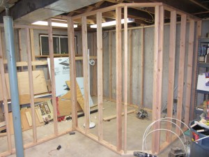
Framing Completed

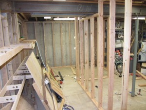
As of earlier this afternoon, I’ve actually completed all of the 2×4 framing that will hold up the CRNW.   Now I need to complete the grid and roadbed, and then I can get down to fun stuff like trackwork again.

The first shot is looking at what will eventually be the Chitina Yard on the top level and Abercrombie Canyon on the bottom level.  The second shot is looking down the long straight-away, with Gilahina on the top rear, Eyak on the bottom left rear, Alaganic on the bottom right, and Strelna on the top right.

The next problem is to either use or junk everything in my extra lumber pile.  I had to move it up against the completed grid in order to install the framing, but now I need to either use it or junk it as it’s in the way.  Once I get that solved, then I’m nearly out of ripped dimensional plywood lumber, so I need to make more.  The problem is that it’s damned cold outside in the winter, and as you can see, there’s not much room to run 4’x8′ sheets through a table saw in the basement anymore.

crnw-framing-complete-1 crnw-framing-complete-2