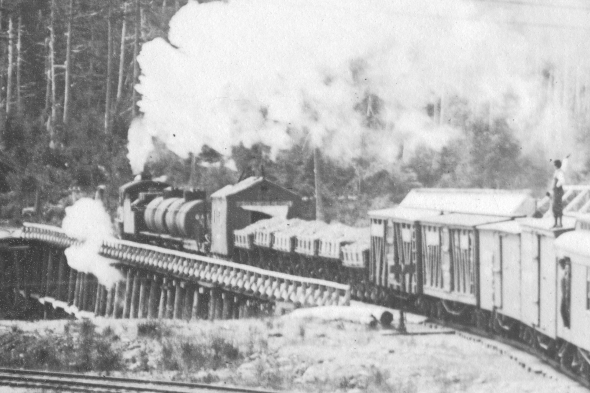
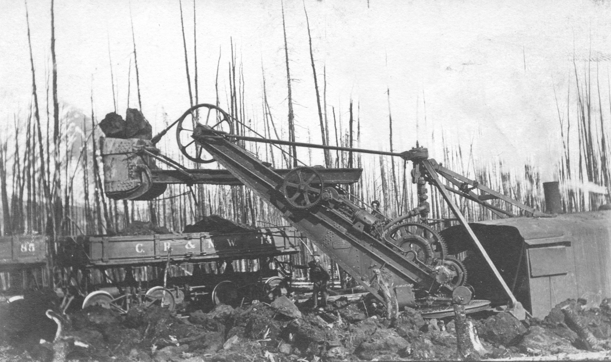
A few recently acquired photographs landed in my mailbox today. I’ll post them over the coming weeks. The first one is one of the CR&NW’s steam shovels loading rock into side dump car #13, with car #85 right behind it. The location and date are unknown, but judging by the trees it looks like a forest fire has been through the area recently.
Records of forest fires in Alaska from these early years are pretty sparse, as there was little way to monitor and track them systemically. However, we know the Gilahina Trestle burned in 1915 from the Sourdough Hill fire, which was attributed to the railroad and burned some 384,000 acres from Chitina to Kennecott. There was also the 1915 Kennecott Fire, which burned 64,000 acres between the Kennicott and Nizina rivers. Still that’s just a guess, and even if correct doesn’t really narrow it down.
A CR&NW steam shovel loads rocks into several side dump maintenance cars.
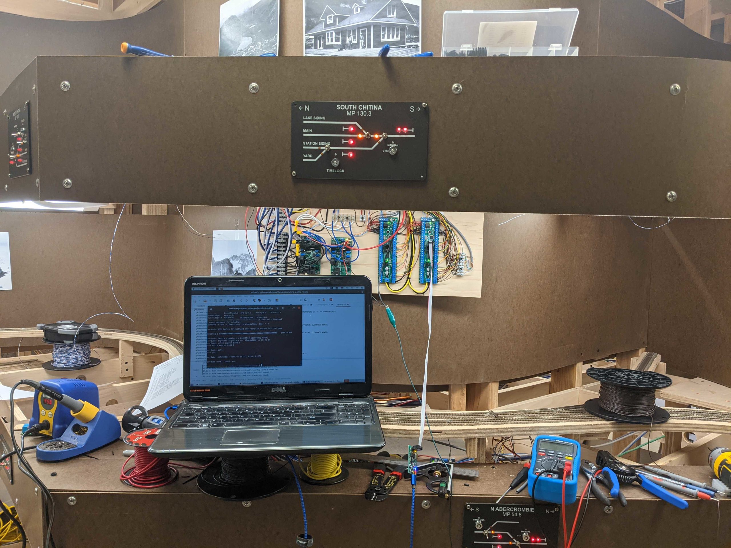
While I haven’t posted much lately, work has been continuing slowly in and around work and personal commitments. I’m pleased to say that I finished configuration and checkout of the final control point tonight at South Chitina. CTC now works over the entire length of the mainline. (The actual trackside signals will be installed once base scenery is done – for now it’s just the fascia signal repeaters.) Most of the rest of the electrical is also complete. The only thing really remaining is to create and wire control panels for the various yards. Then it’s on to starting scenery.
The signal department at work, configuring the South Chitina controller
I was cleaning part of my workbench today and ran across the camera car I hacked together back in 2016 to do my original “tour around the layout” video. I wouldn’t call it a great camera, but it’s relatively small and it produces okay video for its size. My other option was keep installing switch machines and track wiring in the Eyak smelter yard, so putting together an updated cab ride sounded like more fun.
Unlike the last one, which started at Kennecott, this one will start out on the (fictional) Nizina Branch and enter the main line at Nicolai Junction (again, fictional, and between McCarthy and Kennecott). The Nizina Branch is located above my workbench, and provides some staging room and a little more operational variety for ore trains from “other mines” up around Dan Creek.
From there, it’s an engineer’s view all the way to Cordova. Stay tuned at the very end for a couple bloopers. Turns out my camera car is far wider than the loading gauge for a typical N scale car and a bit top-heavy, so it doesn’t always behave itself now that some of the layout clearances have gotten a bit tighter.
Some 11+ years ago, I started messing with servos and PIC microcontrollers as switch machines. Originally it was just for Ron Renner’s Wind River in Denver, where we didn’t want to spend the money to upgrade all the twin coil machines to Circuitron Tortoises. In an afternoon, I had a primitive workable design, and Ron’s layout eventually got dozens of them installed. Each was hand-built and installed in place using double-sided foam tape for both the servo and the PCB.
Those early prototypes then went on to become the basis for Iowa Scaled Engineering’s MRServo line a couple years later. The MRServo matured over the years, moving to surface mount components and then proper 3D-printed mounting brackets to make installation more reliable. But fundamentally, the design remained little changed from the earliest units.
The very first MRServo prototype, hand-wired on a piece of perf board with a demo turnout on a stand.
My very first servo switch machine prototype, back in the summer of 2011
The first servos actually installed on Ron’s Wind River RR back in September 2011.
Iowa Scaled’s first attempt at MRServos, with way too many through-hole parts for economical manufacturing.
The final commercial version of the MRServo from ISE, the version 3
We (Iowa Scaled Engineering) discontinued MRServo about three years ago because sales had tapered off, more large players had entered the market (Walthers) and we never got any sizable market share away from the dominant vendor, Tam Valley. There was nothing about our offering that was fundamentally compelling and differentiating from the others. Plus they were a pain to build and support for relatively little profit margin.
The MRServo Version 4
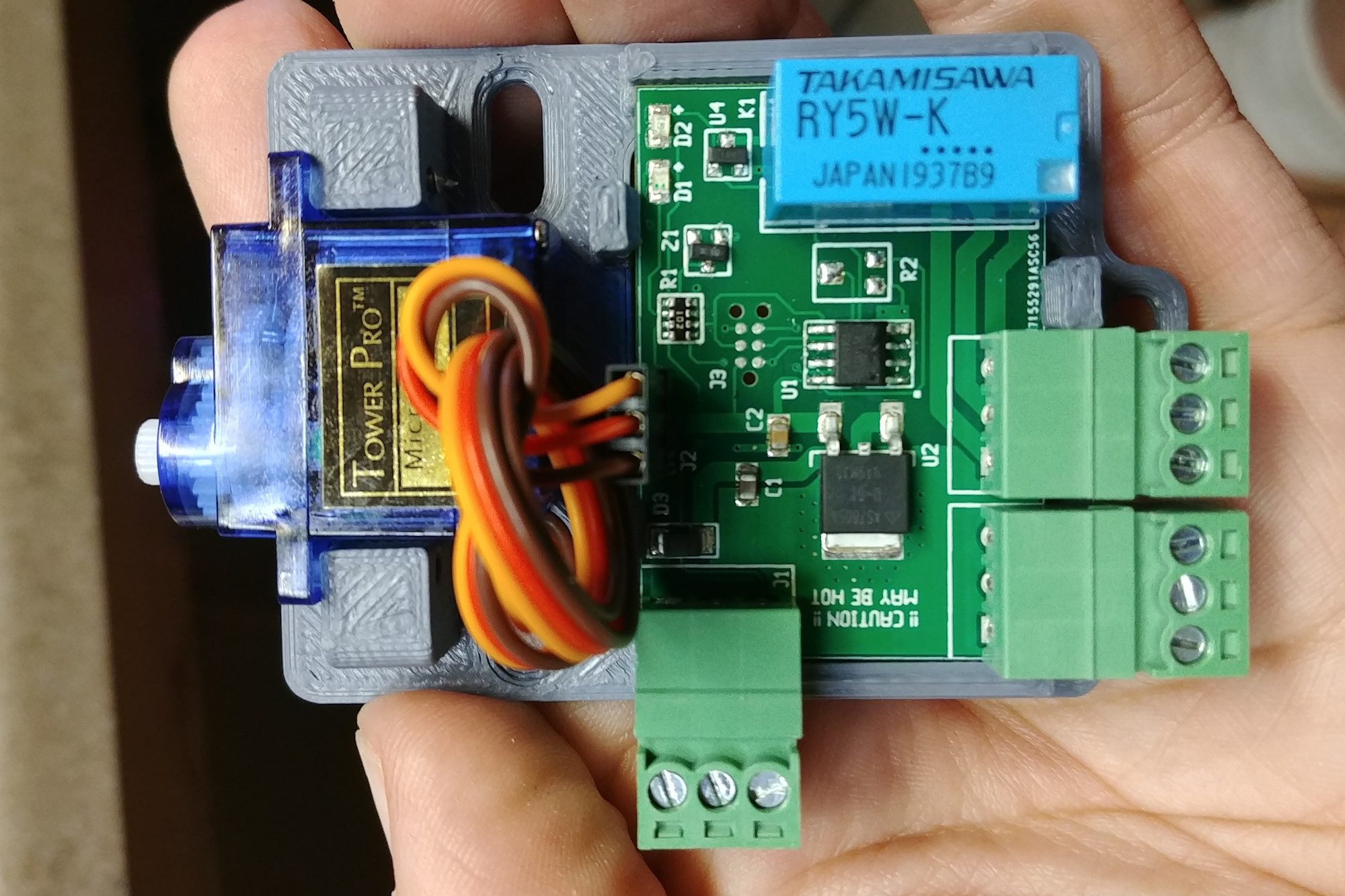
That’s not to say MRServo died, though. It just went from being a product back to a project. My layout still uses them exclusively as switch machines, with probably close to 100 installed. They’re great for me because they’re relatively inexpensive (especially if I’m building them myself), they’re low profile (so they fit up inside the benchwork without issue), and they take a logic level input to control them (so they’re easily run by the signal system). A few months back I got the itching to again improve the design. I wanted to improve the input protection structure, which often got static-zapped, and also move to an AVR so that I could make changes in C rather than PIC assembly. When I designed the original servo controllers, I was still using PICs regularly and programming in their assembly variant. However, having gone to AVRs and GCC around the same time, I haven’t used a PIC in a new design since.
One other minor change is that I’ve started putting 2-piece terminal blocks on the boards. That makes it significantly easier to connect wires under the layout, as I can pull out the connector, screw in all the wires, and then just plug it back in.
The newest version 4 of MRServo, including an upgraded microcontroller, better input protection, a surface mount regulator, and detachable terminal blocks for easier wiring.
Like all of its predecessors, the MRServo v4 is open hardware. The source code and design files are all available on Github.
Since I haven’t posted pictures of the whole layout in quite some time and it was all nicely cleaned up for the CR&NW’s first work night last week, I thought I’d show you the state it’s currently in. The track is complete, except for a few spurs and industry tracks that have yet to be positively defined. The backdrop and fascia is 99% complete. The lighting is done, the signaling is 95% done, and track power wiring is 95% done. I’m still installing switch machines at Chitina and Cordova, but that should be done in a week or two. I’ve also posted pictures on the backdrop to inform others and remind myself what some of the scenes are supposed to look like. It’s a combination of my photos from visits over the last decade combined with historic imagery.
Once I get those last few benchwork and electrical to-dos resolved, it’s on to scenery and painting!
To the right as you walk in, Chitina is on the top and Abercrombie is on the bottom. The helix is hidden in the middle.
Walking into the layout. McCarthy/Kennecott are on the upper deck to the right, the Cordova docks on the bottom. In the center are the Million Dollar Bridge (Miles Glacier) on the bottom and the Chitina (third) Copper River crossing on the top.
Looking the other way down the Cordova / McCarthy yards, along with the new Nicolai Jct CTC repeater on the top fascia and McCarthy in the back.
McCarthy on the top, Kennecott on the top left. Cordova on the bottom right. The peninsula sticking out that you can barely see is the Kotsina hill on the top and between Alaganik and Miles Glacier on the bottom.
Looking down the long aisle. Left bottom is Eyak and the fictional smelter complex, top is the run between McCarthy and Chokosna. Right bottom is Katalla Jct, top is South Strelna.
Looking back up the long aisle, Eyak on the bottom right, Gilahina on the upper right. Strelna upper left, Alaganik lower left.
From the stub aisle at the end, the Eyak complex is on the bottom straight ahead, Alaganik on the bottom left, North Strelna on the upper left, and Kuskulana will be immediately to my upper right and out of frame.
The stub aisle at the end of the long aisle. Alaganik at the lower right, North Strelna upper right. Kuskulana upper left (fascia yet to be cut out all the way down) and Mudhole will be in the back left corner.
The prototype CR&NW, running only a through train or two every day even at the peak of operations, never really had a use for signals. Operations were handed with train orders telegraphed to stations, and honestly from all evidence that survives, it worked just fine. There’s no record of any major cornfield meets anywhere on the CR&NW during its ~30 years of operation. (An astute observer may try to point out that there are no cornfields on the CR&NW, but my point holds.) The only signal we know of on the original line was a wigwag crossing signal in Cordova.
The N scale CR&NW, however, was always intended to be signaled. I love signals. I’ve been fascinated with them since I was a kid. I have two full size signals in my back yard and part of one in my kitchen. Since my Copper River is set nearly 80 years after the original went out of business, I can take a few liberties with how the line evolved. Plus, with keeping 3-4 operators busy during operating sessions, that’s going to be a fair amount of traffic in only ~10 scale miles of track.
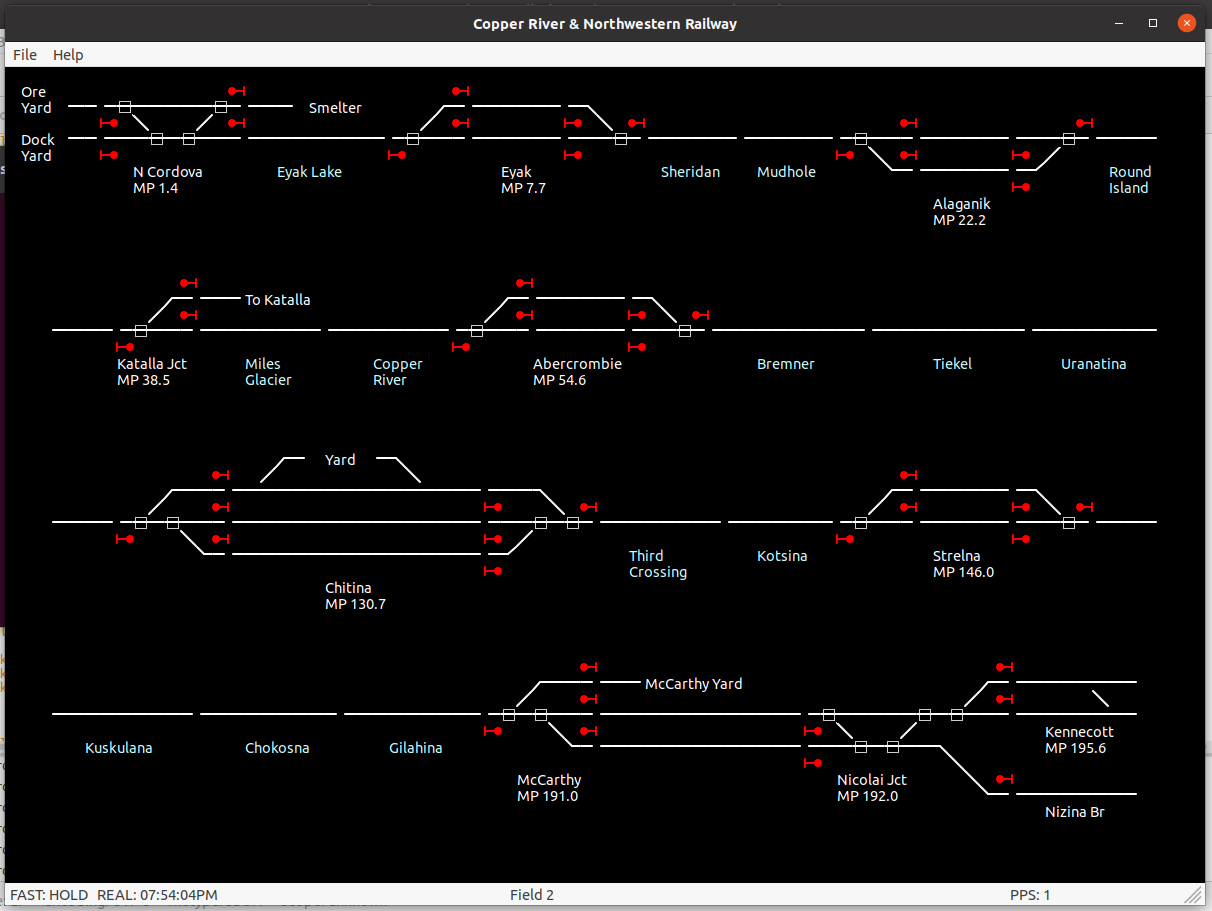
I’m going to write a series of articles on the operation of and the technology behind the system over the coming weeks, but in the meantime I’m going to put up a screenshot of the Computer-Aided Dispatch (CAD) system that will be used by the dispatcher to route traffic. Visually it’s very nearly complete, and about 75% of the functionality is there under the covers. The display is a little boring since I’m developing it from Iowa and while it’s communicating with the layout back in Colorado, the layout is mostly not on and thus not sending any data back. The fast clock is the only thing up and running.
I’ve always liked the idea of fascia signal repeaters, just so operators on through trains don’t need to push to push their way into every corner just to see those inevitable awkwardly-placed signals. Is it prototypical? Probably not, although in either cab signal territory or now as we’re pushing into the new world of PTC, it’s not that far off. It just makes for a smoother operating session, in my opinion.
One option is 3 LEDs per signal head – one for each major color. That’s a lot of LEDs to make room for on the panels. Another option would be red/green bi-color LEDs, energizing both to get a mixed fake yellow color. That has the advantage of one hole per signal head, but the problem is there’s often significant variation from one LED to the next (requiring tuning the color of each individually), and they have a strong color shift based on viewing angle. What I really wanted was a true three-element LED, with true red, amber, and green emitters. The problem is that most of the very few true red-yellow-green LEDs are surface mount, which doesn’t lead itself to being installed in fascia panels.
There is one option, though – the Lumex SSL-LX5097SISGSYC. It’s a standard 5mm LED, albeit with four leads, and available off the shelf from Newark. The red and yellow are reasonably bright, but the green element is a bit weak. Still, some experimentation on the bench showed that they were more than bright enough for panel indicators, and with the proper resistors could be nicely evened out to the eye. At 5V, putting 1k on the red lead, 560 ohms on yellow, and 220 ohms on green provided subjectively even indication brightness.
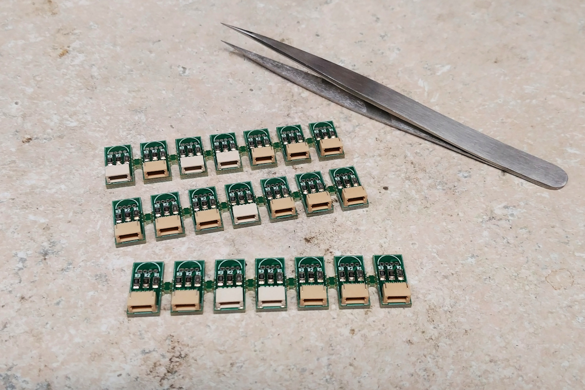
Since I didn’t want to solder resistors and leads on to something like 60 LEDs, I built a small PCB that integrated a place to mount the LED, the three dropping resistors, and a small JST SH-type 1.0mm 4 position connector. Panelized into groups of 7, it cost me $30 to have 210 individual boards made at PCBWay. After that, it was a matter of getting a solder stencil, slathering on paste, placing components, and then reflowing them in my toaster oven that’s dedicated to PCB manufacture. For those interested in making their own, the schematic, PCB, and Gerber files are all under the “ckt-sigcon” files in the ISE CKT-SIGNAL project on Github.
Three ckt-sigcon panels assembled and ready to go on the bench.
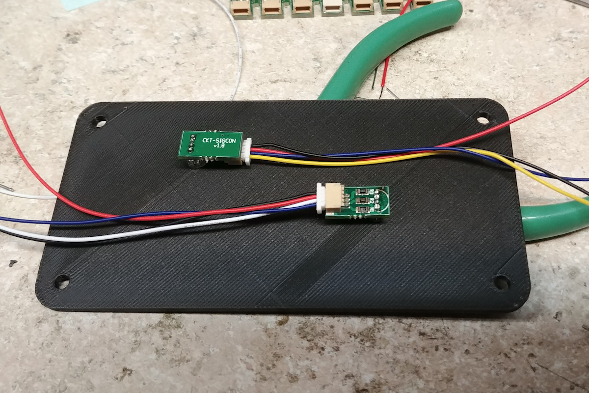
Once assembled, it was a simple matter of soldering in the LEDs and installing them in some of the new control panels that we’ve been 3D printing. Connections to the little LED boards can then be made with 4-wire cables available from a number of sources. I have a large supply, since Iowa Scaled Engineering uses them for connecting to our newest versions of the TrainSpotter detectors. However, Sparkfun also sells them for their Qwiic I2C network system, and I’m sure you can find more sources. Ours are custom made by DirtyPCBs.
Two signal repeater LEDs installed in the back of one of the panels. I was experimenting as to which side I wanted the LED mounted on, hence why the two boards are on upside down. I settled on the upper configuration – with the parts toward the panel – being the preferred orientation.
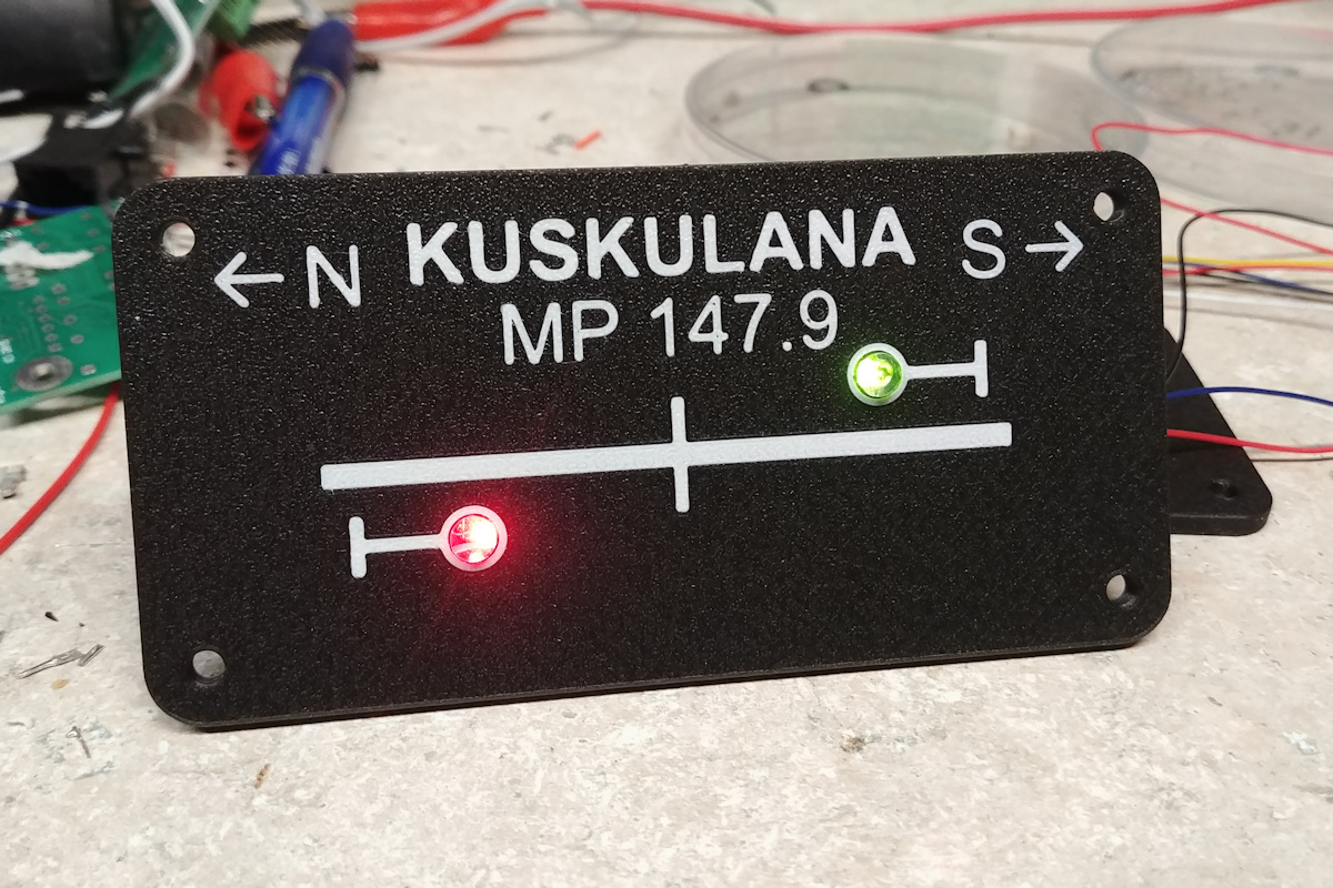
The end result is a very nice looking signal repeater panel with very clear indications in both normal room lighting and in “night” mode.
The signal repeater panel for the Kuskulana intermediates, which will be located at the south end of the bridge.
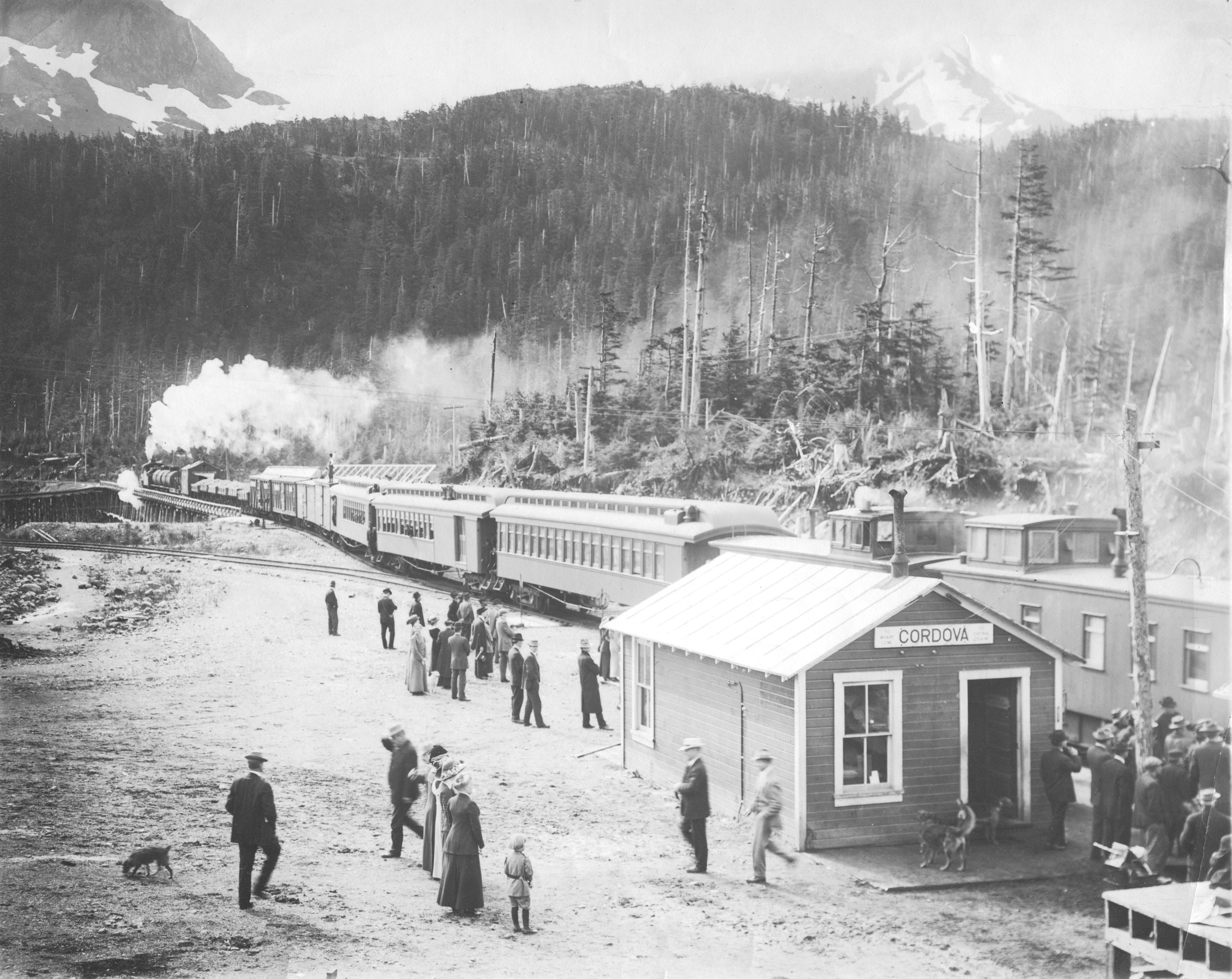
Here’s an interesting old photo I picked up last week – a CRNW train leaving the Cordova depot. For those who don’t know, the Cordova depot was located at the bottom of the hill on the south end of First Street. Hand-written notes on the back of the image indicate this is August 8, 1913.
Leaving Cordova on Friday, August 8, 1913
There’s a couple interesting items in this photo. The first and most obvious is the fact the fourth car back from the engine appears to be a house. Zooming in, it appears that the CRNW is moving some sort of structure north on a depressed-center flatcar, and notes on the back call it a “house”.
Other interesting bits are the two GATX tank cars immediately behind the engine, which were used to deliver fuel oil to Kennecott. I wish I could see the number on the rear car, but at least this confirms the CRNW tank cars were GATX. Then behind the house on the flat are six of the 20t Western air dump cars loaded with what appears to be gravel. My guess is that this is gravel from the pit on the north side of the Odiak Slough and the yard being moved up the line for filling trestles and shoring up the early track.
Also of interest is the Cordova station sign. It shows “TO WHARF 1.3 MI”, which makes perfect sense given that the wharf is the end of track. However, on the other side, it shows “TO CHITINA 129.4 MI”. It’s interesting in that this shows the railroad, at least when it was painting this sign, still viewed Chitina as a junction between the railroad’s main line (Cordova to Chitina, with future expansion northward) and a branch over to Kennecott.
Now that the fascia is all there, it’s time to start mounting control panels. This is one of those things I’ve been agonizing about for some time. My traditional method involves printed track diagrams sandwiched between two pieces of acrylic and bolted into the fascia. I’ve never liked it, because inevitably the acrylic gets scratched or cracks, the print on the paper fades or the paper yellows, and they’re just a pain the butt to actually build because of all the cutting and drilling that must be done precisely.
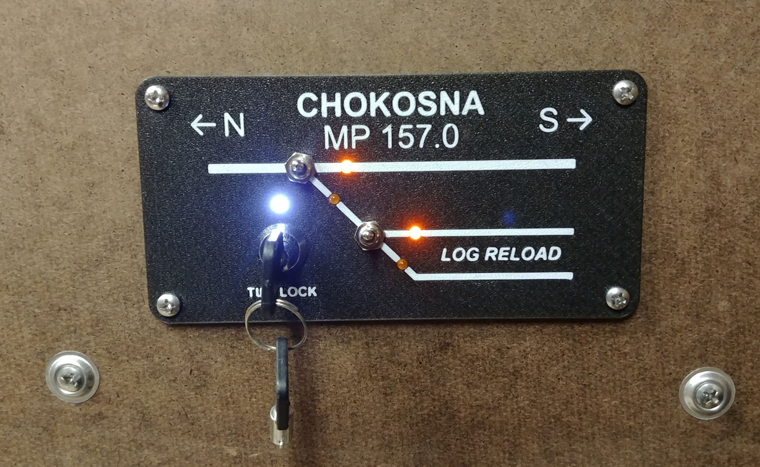
Michael came up with a novel idea when I was visiting ISE World Headquarters a few weeks back. Basically the whole thing is 3D printed, and the track and lettering is printed using a different filament color. We don’t have a Prusa i3 with the multi-material upgrade yet (it apparently shipped today), so filament changes are currently handled manually. However, the holes are just made as part of manufacturing, and since the track and lettering is literally molded into the panel as part of the print process, it’s almost indestructable.
Here’s the Chokosna lumber reload spur panel…
Right now, we’re printing them using white and “glint grey” PLA on a textured Prusa bed to give it a finished texture. The indicator LEDs (amber for turnout position, white for timelocks, other colors to come…) are 3mm pre-wired LEDs I found on Amazon.
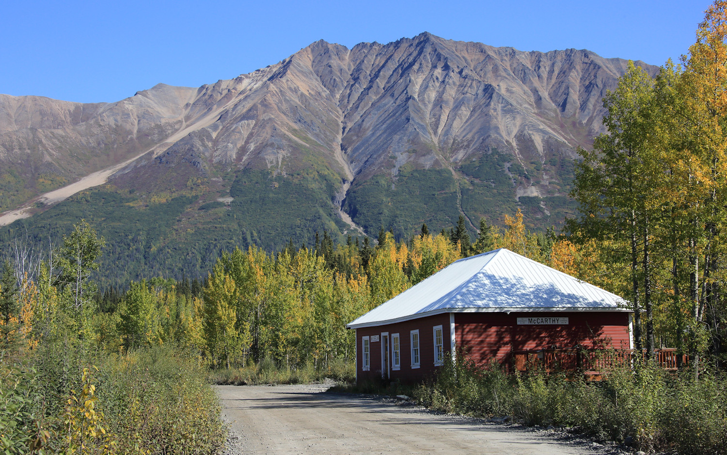
My phone and Google reminded me this week that five years ago, I was up in CR&NW country at Kennecott. Alternately seems like ages ago and yesterday all at the same time.
The preserved McCarthy station building, now the local museum.


 on the bottom and the Chitina (third) Copper River crossing on the top.")


 and Mudhole will be in the back left corner.")