In addition to track power, which is something most of us have provided by our DC throttles or DCC systems, most of us have a ton of accessories. That can be as basic as things like switch machines or a hodge-podge of building lights, animated features, signals, sound modules, etc. Nearly every single one of those is going to have its own requirements in terms of voltages, currents, etc. Most layouts I’ve ever been on solve this by a maze of power strips, wall warts, battery packs, and old DC power packs repurposed once the owner converted to DCC. It’s a mess.
As an electrical engineer, some things about how people build layouts bug me far more than they should. Messy, disorganized power systems are definitely at the top of the list. I thought I’d give you a look at how power is distributed around my layout to run everything that’s not the track.
The 24V Power Bus
Nearly 20 years ago, I first met my late friend, Ron Renner, up in Denver. Not being an electrical guy, and not having an electrical guy on the layout crew, his Wind River Railroad was particularly bad about power supplies everywhere. A few years after operating up there and building him a fast clock system, I started working on modernizing the electrical system on the layout. The arguable goal was to install signalling, but first I had to deal with the electrical rats nest under the layout to even figure out what was what. I quickly decided power supplies everywhere needed to go – particularly after reaching under the layout and coming in contact with a toggle that switched 120 and wasn’t insulated.
So I decided that there would be one core power supply in the CTC panel’s guts, and it would distribute power around the layout and converters would be installed near the individual loads to provide for their individual voltage needs. Everything would feed off this one auxiliary layout power bus.
I picked 24VDC because it was relatively safe. Nobody’s going to get hurt if they come in contact with it, but it’s sufficiently high to move power without high resistive losses in the wiring, and it’s higher than pretty much anything on a layout needs to operate. It’s also low enough that it’s easily within the safe input range of low-cost DC-DC converters.
Power on the Copper River
When it came time to power the Copper River, there wasn’t any question – a 24V aux power bus would be the answer. There would be one core 24VDC power supply mounted to the electrical panel. That power supply would feed power districts, roughly centered around the large operating areas of the layout with lots of signals, switch machines, etc., and I’d convert power down in each station’s electrical panel.
The Power Supply
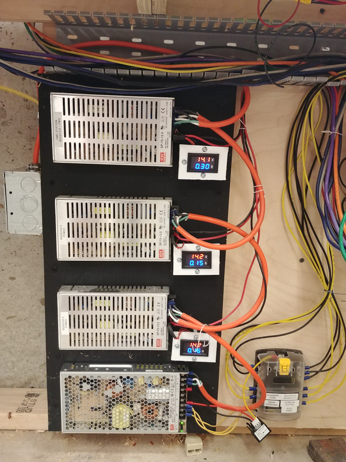
The power supply of choice was a Mean Well RSP-200-24. The supply takes in 88-264VAC and converts it to 200W of clean 24VDC power. While you can get cheaper 24V open frame power supplies, Mean Well is a known brand and their supplies really have passed all the necessary safety and EMC testing. The RSP-200-24 runs between $40-50, and is available from a wide variety of sources. Mine came from Mouser.
The 24V power supply is at the bottom of this stack – the upper three are SP-75 13.5V power supplies (dialed up a bit) to feed the three DCC boosters. They’re mounted to a piece of fire-retardant Kydex plastic, which is then offset from the plywood back of the electrical panel. That way if one of them decides to end its life spectacularly, there’s something between it and bare wood. Eventually there will be a cover over them as well to prevent anything random from coming in contact with them (as there is exposed 120V mains here), but it’s not mounted yet.
All four have voltage-current meters attached to them so that I can see performance at a glance, but since the 24V supply is bigger, I haven’t mounted the meter for it yet. It’s just sort of hanging there.
The Fuse Block
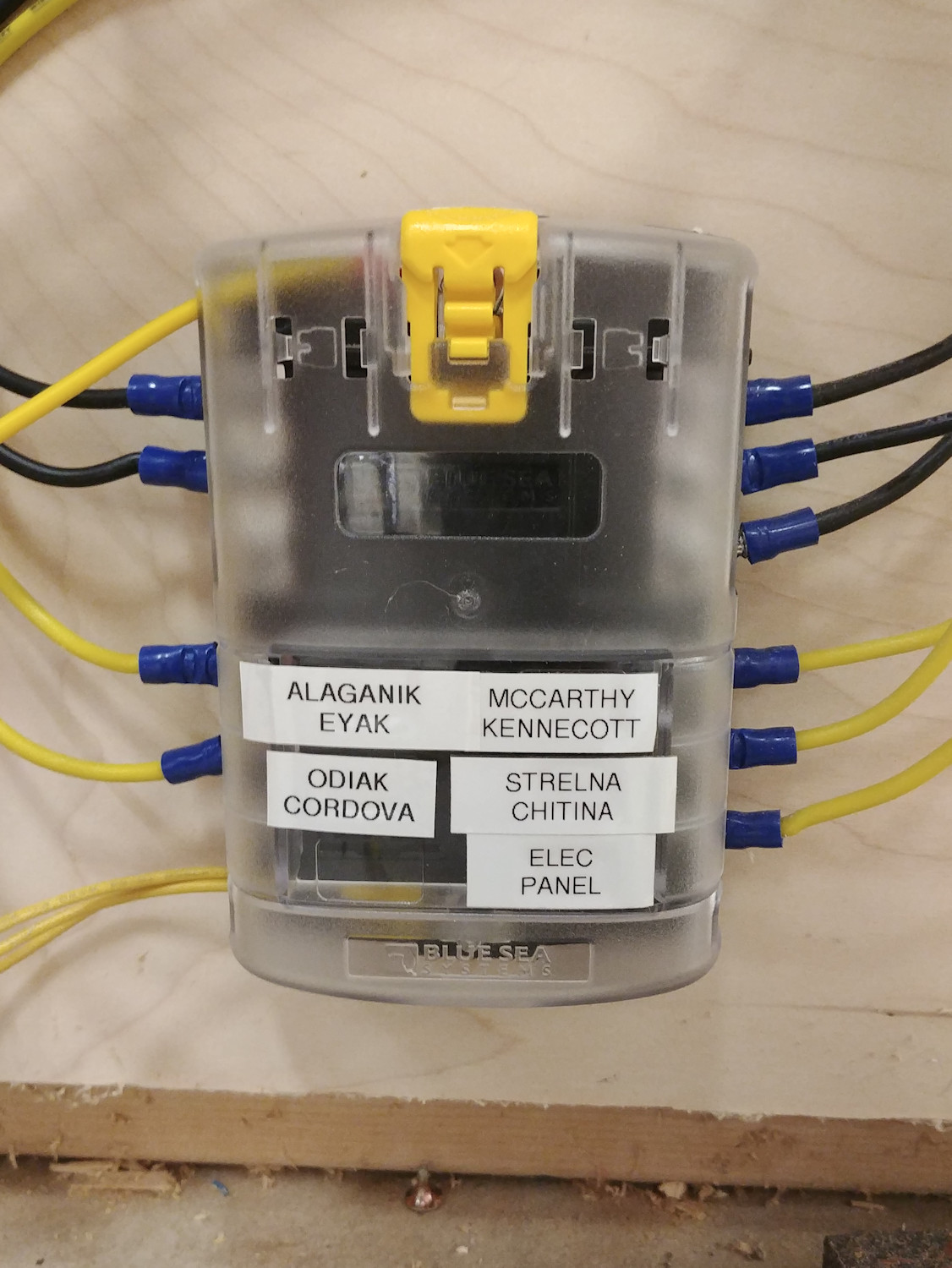
From the power supply, the 24V goes into a fuse box. Yes, 24V can’t electrocute you, but 200W of 24V is still 200W, and can turn unexpected things into an incendiary device damn quickly if something shorts or fails. So I use a small 6-circuit fuse block from Blue Sea Systems, who makes electrical components for boats. It’s a nicely built little component that takes standard automotive blade (ATO/ATC) fuses.
Each of the major districts on the layout gets a branch circuit and its own 2A fuse. Those districts are currently:
- Alaganik & Eyak
- Odiak & Cordova
- McCarthy & Kennicott
- Strelna & Chitina
- One for the electrical panel’s own needs
- A spare for future use
A yellow (+24VDC) and a black (ground) 14AWG wire go from the fuse block out to each district.
Local Power Conversion
At each major station’s electrical panel, there are one or more small DC-DC converters that would change the 24V into the various voltages needed for operating accessories in that area. Some things, like the MRB-XIO boards that run the signals, have their own switching converters that can take 24V directly. Other things, like the MRServo switch machines, only have on-board linear regulators and thus would be most efficient if operated at 7.5-8V.
Let me step back for a moment – what’s a DC-DC converter and why use one over something simple like a linear regulator? DC-DC converters – otherwise known as switching regulators or switching converters – efficiently transform DC power at one voltage to DC power at a different voltage.
Let’s consider a load drawing 0.5A at 8V, or roughly 4W (about what an MRservo can draw when the servo is working hard). A linear regulator converts one voltage to another by acting as a big resistor, dissipating the excess voltage as heat. So from a 24V bus, you’d be dropping 16V in the regulator to get down to the 8V. 16V * 0.5A = 8W being dissipated as heat. That’s twice as much as is going into productive work in the load, and you’ve got to get rid of that heat somewhere! In addition, your total load on the original power supply is 24V * 0.5A, or 12W (4W for the load, 8W burned in the regulator).
A DC-DC switching converter converts *power*, so assuming a 85% efficiency, it would need 4.7W in to provide 4W out. Now we’re only burning 0.7W in change between voltages. It does this by storing energy in a magnetic field within an inductor and releasing it over time. The math and physics of this is beyond a model railroad blog, but trust me – it works, and it works really well.
Switching converters used to be incredibly expensive, but in the last 20 years the price has gone through the floor since semiconductor companies have introduced single component solutions that do almost everything. Then the Chinese knocked off those components and produced them for pennies.
If you search eBay for “step down converter”, you’ll get a huge array of little modules for a few dollars that – nominally – are DC-DC step down (go from a higher voltage to a lower voltage) converters. Some (anything that says LM317 or 1117) are actually linear regulators. Some (most that claim to be based on an LM2596) work fine, but are based on really bad knock-off parts that don’t perform well and fail in horrible ways (apply full input voltage to the load) when actually pushed to more than 30-40% of rated power.
However, there are some of these modules – found through trial and error – that actually do work as promised for the most part. In particular, I’ve become fond of the ones that claim to be based on an XL4015 and have a small built-in voltage meter. The XL4015 is made by XL Semi, which is a Chinese company. They’re not lying about who they are or trying to be a knockoff part. It’s a real part with a real datasheet. And, at least in my testing, it seems to actually work as advertised.
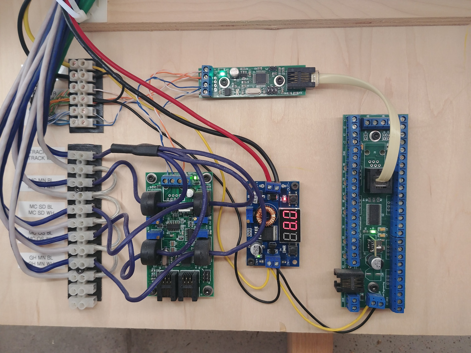
Each station along the line has an electrical panel that folds down from the benchwork, allowing for future maintenance while keeping things out of the way during normal operation. At each one of these panels, there are one or more of these XL4015-based DC-DC converters, happily converting 24V layout power to whatever local voltages are needed. At most locations, that’s 8V for the switch machines. Under the layout, the local 8V supply is then distributed on red (+8V) and black (ground as always) 14AWG wiring.
In this picture – the McCarthy panel – you can see the local power regulator in the middle, showing it’s outputting 8V for the local switch machines.
And that, folks, is how my N scale Copper River & Northwestern gets powered.
Excellent explanation, my layout is wired for accessories as explained however I fall down on not fusing the various distributions (next job for under the layout) also I was not aware of the XL4015 and I assume that the ones I installed use LM 2596 ( looks like a replacement is necessary) .
Thanks for the excellent write up.
Regards
Bernie