Like most layouts, the CRNW will need a variety of voltages scattered about for turnouts, signals, structure and scenery lights, etc. I’ve seen various solutions to this problem over the years, ranging from a single auxiliary power bus with local regulation, to multiple aux power buses running at different voltages, to the worst of all possible options (which I’ve seen on more than a few layouts): various old power packs, wall warts, batteries, scattered all over the place to power everything.
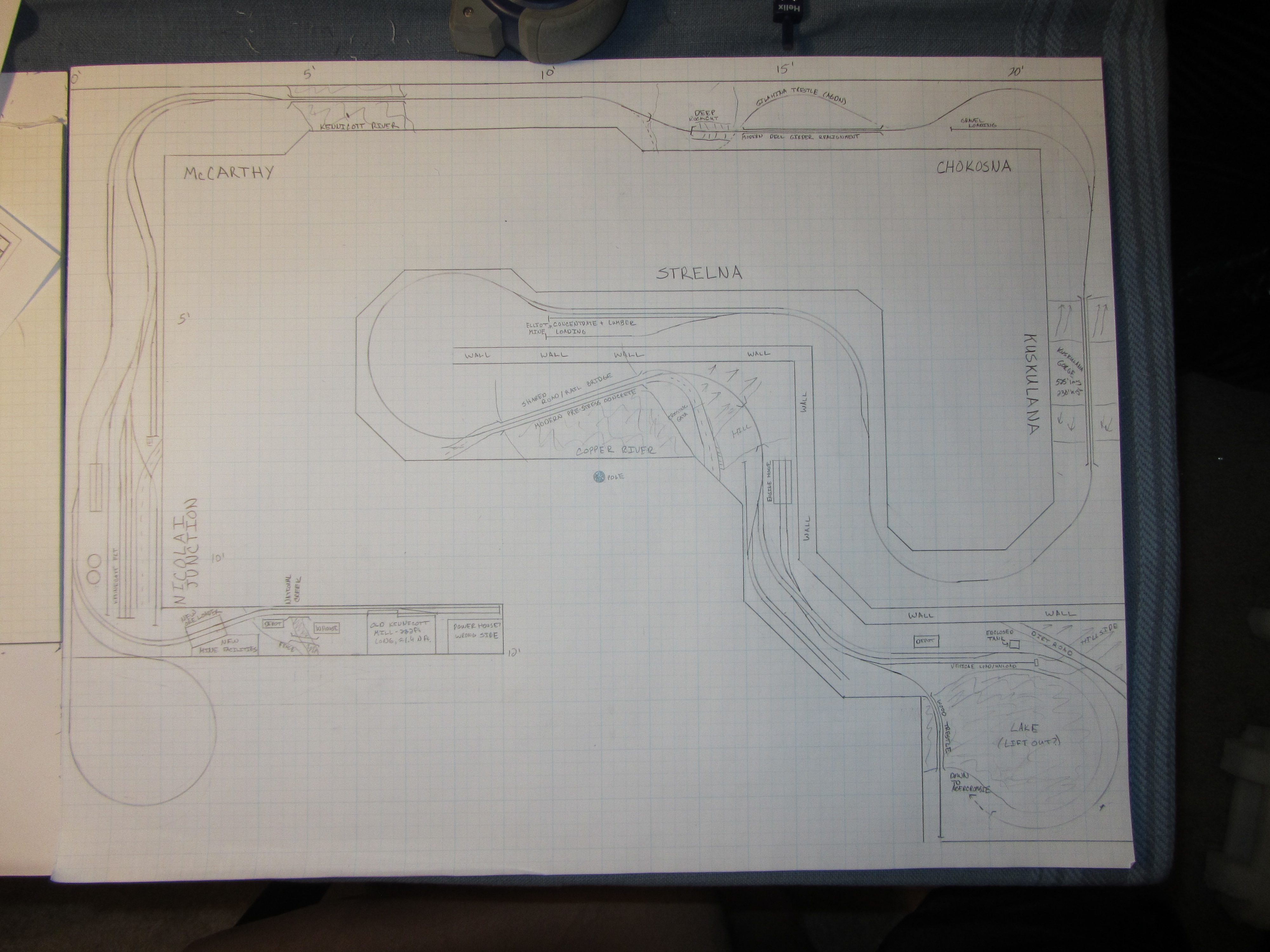
Myself, I’m a single aux power bus sort of guy, with point-of-load regulators to deliver whatever voltage is needed. That way, I can delivery 8-9V for MRBus and MRServos, 3V for structure lights, 12V for local NCE cab bus power injection, etc. and only have to run one large, high power bus around the layout to feed everything. My traditional preference is to run the aux bus at a nice 24VDC. That means using linear regulators for local voltage generation is pretty much out, as you’d burn a huge amount of power in the regulators. As an example, take the Nizina Yard and its two MRServo-2s. They’ll need ~8VDC, and will each draw ~50mA just sitting there if the relays are on (as they’ll be for one direction or the other). That means the two turnout motors will be drawing 0.8W (8V * (0.05A * 2)), but the regulator needed to create the 8V will be burning 1.6W ( (24V – 8V) * (0.05A * 2) ). That means that my point-of-load regulator is only 33% efficient. And it only gets worse from there.
The answer to this is something called a switching regulator (aka a switchmode power supply or simply “switcher”). Basically, rather than burning off the excess electrical power as heat, switching regulators convert that excess to a magnetic field. For some small amount of time, they’re switched on, powering the load and storing excess energy in building the magnetic field. Then they switch the input off and power the load by collapsing the magnetic field. If you change the ratio between the on and off times and do it very quickly, you get very good regulation and a large percentage of the power actually gets delivered to the load. It’s not uncommon for switching regulators to be 90+% efficient, which is why they’re becoming common everywhere.
The problem with switchers is that they’re much more complicated than linear regulators, and thus typically more costly. Fortunately, Chinese manufacturers do things on scales that boggle the mind and do it with parts that are sometimes of questionable heritage, driving costs to an insane minimum. Popular on eBay are switching converters based on fake National Semiconductor (now Texas Instruments) LM2596 parts. Often available for around $1 in small quantities, these are a full, adjustable output switching converter on a small PCB, including the control chip, inductor, input and output capacitors, diode, and a potentiometer to set the voltage.
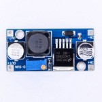
Typical eBay fake LM2596 module
However, now’s an appropriate time for a disclaimer. One of my favorite quotes from a movie character is from Burt Gummer (played by fellow model railroader and actor Michael Gross): “The possibilities for disaster boggle the mind…” At the prices offered for these boards, the LM2596 parts used are almost unconditionally fake, Chinese cloned parts, thrown together into a module where every corner has been cut and every substandard part has been used to minimize costs. As such, it doesn’t behave like a real quality National/TI part, specifically when you start pushing the limits with regards to current and temperature. Specifically, if they get too hot, they don’t shut down like a real one. They just short, sending full input voltage to the load. If your load can’t handle it, it goes up in smoke. However, I’ve used a lot of them on various model railroad applications over the years, and as long as you use them conservatively (meaning don’t do more than 1A continuously), they do work and work well for $1.
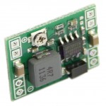
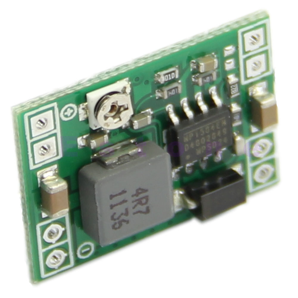
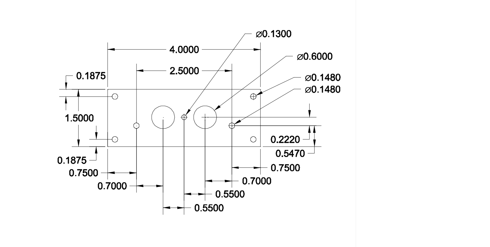
eBay MP1584EN module
A new module started appearing on eBay a couple months ago – a much smaller design, based on (theoretically) a much more modern switching chip. The chip appears to be an MP1584EN from Monolithic Power Systems, and the board is about the size of a quarter. Again, they’re available for about $1, which makes no sense at all, given that real MP1584EN parts are over $1 even in 10,000 unit quantities, and that doesn’t take into account the other parts, the board, or putting it all together. Either the Chinese got a hell of a steal on their parts, or once again we’re dealing with a cloned part. So what did I do? Order a dozen of them for evaluation, of course!
In the usual 2-3 weeks, a bag showed up in the mailbox with a whole bunch of the little modules in it, each individually packaged in an ESD protection back. Each module is about the size of a US quarter – exactly what the dimensions on the original eBay listing promised. However, the holes are not exactly where they were specified to be – the upper and lower groups are 30 mils too far apart and the right and left groups are also 30 mils too far apart. Otherwise, they’re pretty unremarkable. So, the next step was to solder up wires and beat them up electrically to see if they’d survive layout use.
The test setup involved a bench supply pushing 24V, meters for input voltage and current, a meter for measuring IC temperature on the switching board, and then a programmable current load (the Re:load Pro from Arachnid Labs – a remarkable piece of gear for the pricetag) for actually sinking the power. Oh, and we’ll throw my scope on the output to check for ripple as well. What you wind up in terms of bench litter looks something like this:
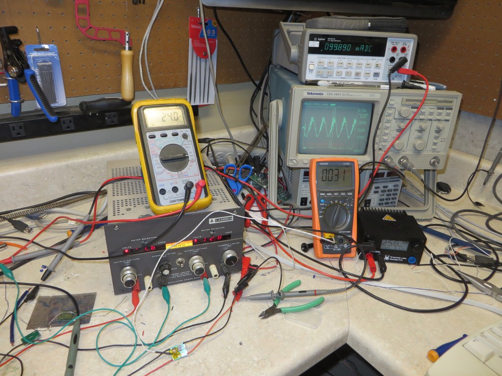
The test setup on my bench
The first one was dead, straight out of the ESD bag. It had quiescent current draw (200uA or so) but no output. Didn’t matter if I twiddled with the pot or anything, it was just pain dead. I suspect the IC itself had a bad power switch, as I couldn’t see any voltage on the output to feed the inductor. Well, write that one off as a mechanical sample only…
The second one fired right up and did exactly what it was supposed to. For the simulation, I chose 24V as the input voltage, matching my planned accessory bus, and 8.5V as the output voltage since that’s usually what I feed to MRServos and to the MRBus network. At each current step, I’d set it and go do other things for five minutes to allow the temperature to reach steady state. (The room was approximately 68F / 20C during the testing.)
Here’s the raw data:
| Target Current |
Vin (volts) |
Iin (amps) |
Vout (volts) |
Iout (amps) |
Tsteady (deg C) |
Vripple (mV rms) |
Eff (%) |
| 0.25A |
24 |
0.1 |
8.47 |
0.249 |
31 |
11.9 |
87.9 |
| 0.50A |
24.1 |
0.196 |
8.45 |
0.499 |
35 |
15.8 |
89.3 |
| 0.75A |
23.8 |
0.296 |
8.43 |
0.75 |
41 |
16.1 |
89.7 |
| 1.00A |
23.5 |
0.398 |
8.41 |
1 |
47 |
16.6 |
89.9 |
| 1.50A |
23.9 |
0.588 |
8.37 |
1.5 |
53 |
18.2 |
89.3 |
| 2.00A |
23.2 |
0.817 |
8.31 |
1.99 |
69 |
20.1 |
87.2 |
At 2A, the part was right on the edge of thermal limiting. It would cut out for a few fractions of a seconds every 5-10 seconds. Above 2A, it was in thermal limiting more than it was out. So realistically, running these at 1.5A would seem to be a safe maximum. Efficiency is also decent – ranging between 87-90% for my test cases. Not bad for a $1 converter board.
On the other hand, the testing proved that thermal limiting does indeed appear to work. Additionally, I subjected the part to repeated short circuits on the output with no apparent harm. It gives me some faith that if this is a cloned control IC or at least one that failed some part of QA (and I have every reason to believe it would be, as discussed earlier), that these actually will function well enough to meet my needs.
Because these boards won’t be very handy to work with directly, and I have a rule that any switching converter hanging off the high current auxiliary bus have a fuse (since a tiny board like this suddenly dissipating 200W+ (10A@24V, my fused limit back at the power supply) seems really bad), I’ve designed a carrier board for them that includes an input filter cap, a ATO-style fuse holder, terminal blocks for the input and output, and a “power on” LED. Pretty simple board, really, but should make working with these things a lot easier. It’s off to fab right now, but I should have it back by Christmas and can report on it as well.


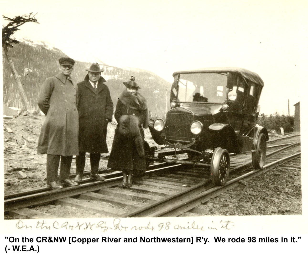
![crnw-modelt-milesglacier_ak-[unknown]-000](https://www.copperriverrailway.com/wp-content/galleries/historic-images/crnw-modelt-milesglacier_ak-unknown-000.jpg "crnw-modelt-milesglacier_ak-[unknown]-000")
![crnw-modelt-milesglacier_ak-[unknown]-001](https://www.copperriverrailway.com/wp-content/galleries/historic-images/crnw-modelt-milesglacier_ak-unknown-001.jpg "crnw-modelt-milesglacier_ak-[unknown]-001")


