Category Archives: Benchwork

Posts related to benchwork

Basic Benchwork Nearing Completion

I realize it’s been nearly two months now since I’ve added an update, but I’ve been rather busy.  For most of May I was actually out of the country, bumming around Germany, Belgium, and the Netherlands for fun and profit (or at least work…)

After getting back, I’ve been working on benchwork and more planning.  The upper valance deck is now all the way around the layout, the middle deck is complete right up to the Chitina Town Lake (where the helix will connect it to the lower level / Abercrombie Canyon area), and the lower deck is complete through the Miles Glacier Bridge.

None of what’s left concerns me all that much, except for the helix.  Helices and I have some uncomfortable history.  My last attempt – while functional – took about four times longer to build than I wanted, wound up being rather expensive, and lacked a certain something in dimensional stability.  This time I think I’m going to go with the threaded rod approach to spacing the decks, rather than trying to screw them all into a semi-rigid wood frame.  Stay tuned…

Lighting & Benchwork Update

Those of you who have been following along know that one of the core electronic pieces I’ve been working on for the CRNW is an LED lighting system tied into the fast clocks.  Over the run of an operating session, I want to transition from “dark” (really dim blue light) through the brilliant warm light of daybreak, the bright white of midday, and the through the golden hour and sunset back to dark.    The system will consist of the fast clocks – obviously – as well as a MRB-GIO to figure out color and intensity, and then a set of power booster boards that actually control the 2000W going to the LED strips.  The power boosters will be local, each controlling <20ft of layout, to keep the amount of power being switched to a more manageable level.

The prototype power booster boards for the LED lights showed up a couple weeks back, but this weekend was really the first chance I’ve had to try integrating them with the full system.  I connected one up to my test LED strip and mounted it back over Cordova, and then connected it to a MRB-GIO and did some basic programming to turn it into a lightning controller.

Results are promising – I need to do a bunch more tweaking on the exact light transitions, but my first try came off pretty well.  I also did a few tests using a bunch more strips to increase load.  The system was designed for up to 6A per channel, so I cranked it up to around that.  Heating was actually less than I expected – the board only slightly warm to the touch even switching 6A on a couple channels.

I’ve posted a few photos of the new power control board, as well as some samples of midday, evening, and night light.  Night isn’t that bright, I promise.  It’s just the camera evened out the exposure.

On the benchwork front, I did get the top deck extended from Strelna over to the north end of the Chitina yard.  The bottom deck is still being pondered – I’d really like to add a short Katalla Branch as a very low level.  The problem is that I can’t figure a way to shove a helix under where the junction should be.  I’m contemplating a train elevator along the wall (hidden behind the Miles Glacier Bridge area), since trains to/from the coal fields above Katalla would be short – 6-8 cars plus power.  Regardless, I’m still pondering it.

Oh well, off to Memphis for the week tomorrow.  I’ll figure out what I’m doing about a potential Katalla branch train elevator when I get back.

Smells Like Progress

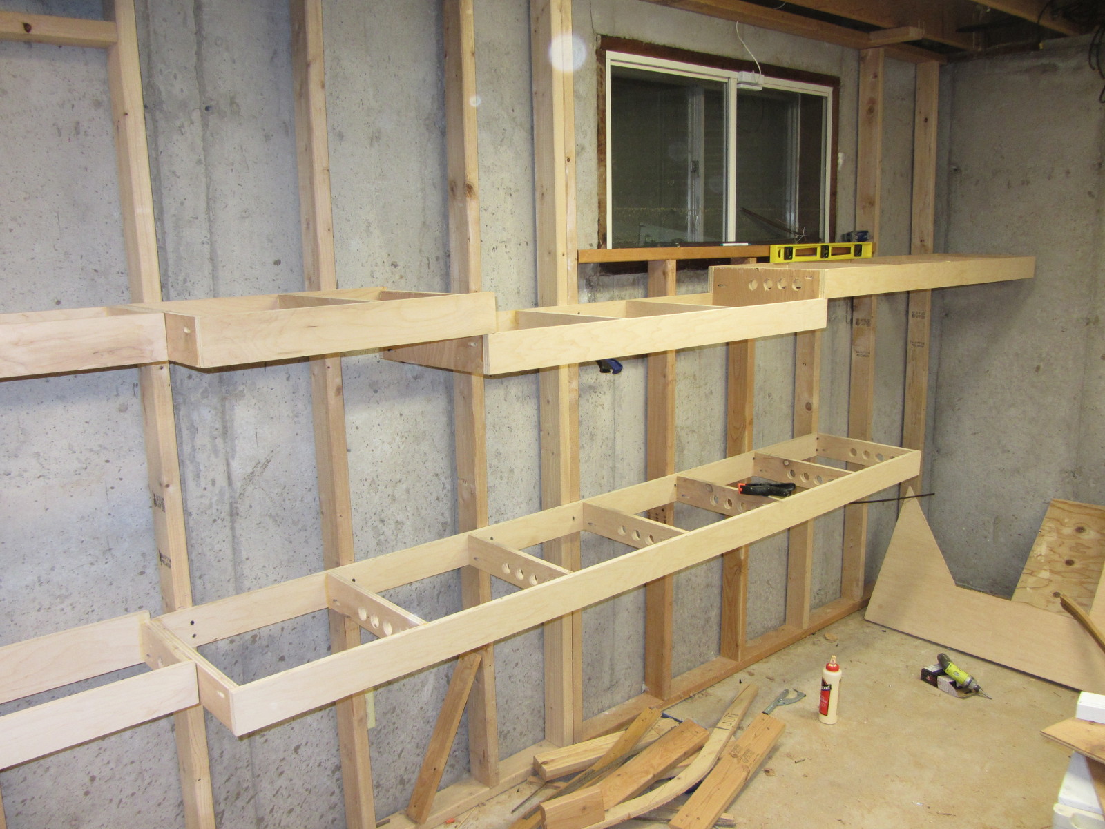
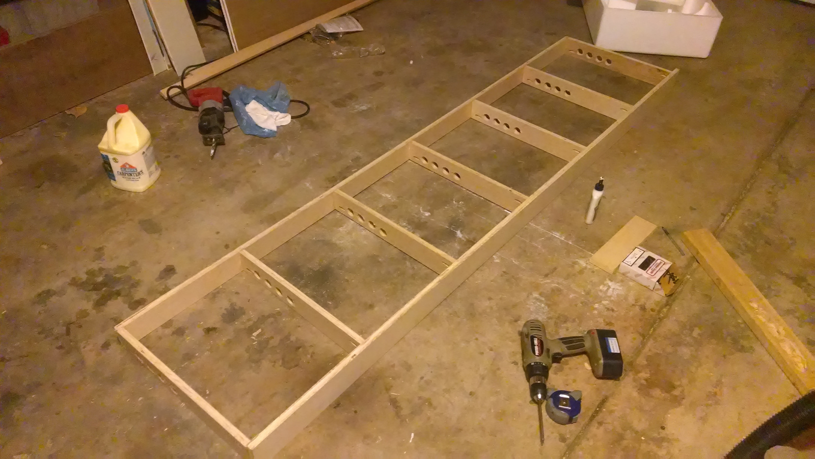
While not feeling the greatest this weekend, I resigned myself to the basement and building benchwork.  As a result, the gridwork is now in place for Cordova-Eyak on the bottom level and McCarthy-Gilahina-Chokosna on the upper level.

Included in the upper level is the first major piece of depressed grid that will accomodate one of the four big bridges I plan to model  – the Gilahina Trestle.  (Photo linked from Don Bains’ Virtual Guidebooks site.)  The other three big bridges being the Miles Glacier / Million Dollar Bridge, the third Copper River crossing, and the Kuskulana Bridge.)  The current version is actually the second trestle – the original burned in 1916 and was replaced by the one we have today.  The structure is ~880 feet long and ~90 feet high on a ~15 degree curve (radius ~440ft.), with six piles per bent and extensive cross-bracing.  Today, it survives alongside the McCarthy Road in a deteriorated state.

For my proto-freelanced version of the CRNW, though, there’s simply no plausible way the trestle would have survived in service to present day.  A 100 year old high wooden trestle is just not up to the passage of heavy ore trains and 200-ton locomotives multiple times per day, no matter how well built or well maintained it may be.  Plus, the trestle forms most of a very sharp curve – much sharper than any reasonable mainline standard.  However, it’s such a stunning visual element along the line, and one that many people who have visited the area are familiar with, so I also can’t leave it out.  My solution is that the mainline will pass by in the foreground, atop a modern deck girder bridge constructed as part of a 1960s-70s era line change (exact date in alternate history to be determined), while the old abandoned trestle remains in the background.  Like many things in the wilderness of the far north, the old is often left just because it’s not economical to tear it down.  Plus, in this case its historical significance to the area in addition to its site within the the Wrangell-St. Elias National Preserve would lend to its preservation.

I’ve had to scale the Gilahina Trestle just a bit.  While 880′ in length, it’s only about 650′ on a straight line between the ends due to the sharp curvature.  (Distances estimated from aerial photographs.)  At full size, it would be approximately 4′ long and 6.75″ high in N scale.  I plan to keep it full height – hence the drop section to give me an extra 3.25″ to play with, but compress the length to about 3′, or 480′ in full size.

If anybody has measurements or plans for the Gilahina Trestle, I’d greatly appreciate hearing from you.  Otherwise I’ll have to head back north and spend some quality time with just me, the trestle, a tape measure, and an ultrasonic range finder.

Here’s a couple shots of the new benchwork grid, including the drop section for accomo

benchwork-eastwallbenchwork-eastwall2

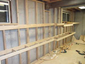
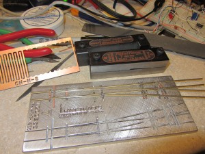
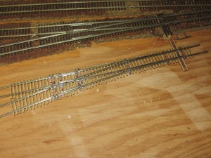
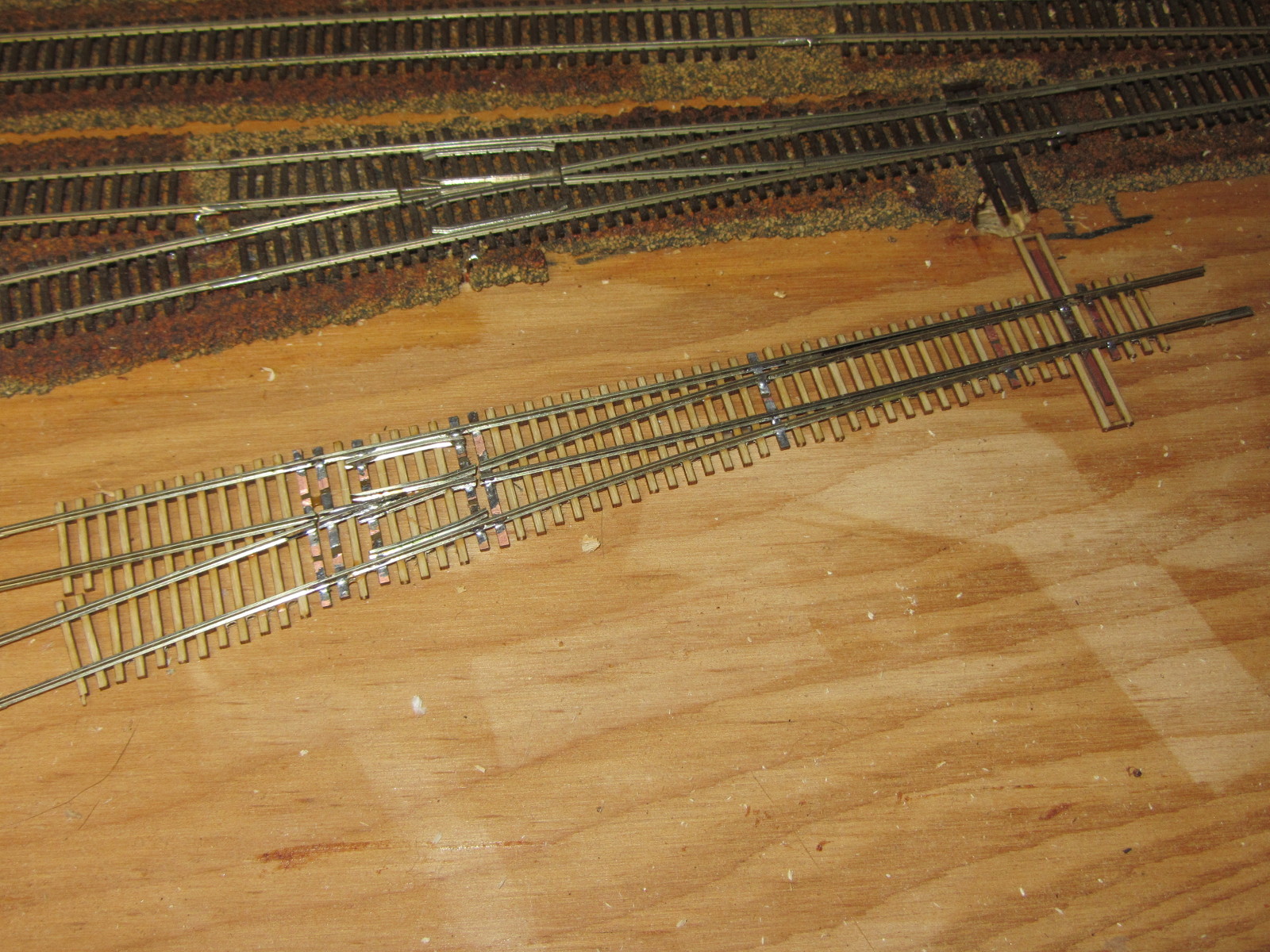
In addition, the Fast Tracks jig finally arrived, and I’ve been practicing at building turnouts.  So far, I’ve built two – one right and one left – and I don’t think I’ve quite gotten the hang of it yet.  Both are usable, but not quite as perfect as I’d like – particularly in the area of getting the point rails just right and making the throwbar move flawlessly.  (I seem to always get the point rails stuck on the stock rail when soldering them, and can never get it deburred once I separate them.)  Also, the FT#7 is a bit bigger than the Atlas #7, leading me to believe the Atlas #7 is really more of a #5-#6.  I’ve put my second attempt next to an Atlas unit so you can do a size comparison.

fasttracks first-scratchbuilt-turnout

Until next time…

Happy New Year!

Like any good model railroader, I spent New Years Day in the basement working on the layout.  I was hoping my Fast Tracks jig would arrive on New Years Eve, but alas, it did not.  So, I reverted to working on lighting, benchwork, and some electronics design.

The good news is that the entire layout room now has proper room lights – nine fluorescent 4′ dual T8 fixtures, to be exact.  It makes it much less of a dingy hole in the ground and much more a presentable layout room.  Now if only the construction disaster would clean itself up…

As far as benchwork, I accomplished a piddly 32″ – the upper deck between McCarthy and the Kennicott River crossing.  The electrical took longer than expected, and I needed to accomplish some design work  for Iowa Scaled for a new optical track detector we’re working on.

My goal for the rest of the week is the rest of the east wall (McCarthy to Kuskulana on the upper and Cordova to Eyak on the lower) and – if the stars align – the rest of the wall framing and clean up some of the random junk in the way of progress.  We’ll see what actually happens.

Construction Update – 9 Oct 2013

As I mentioned before, late September and early October are usually charter season here in Colorado, and consequently I spend more time out on the narrow gauge than in my basement.  So a few teasers as to what I’ve been up to, from this year’s Chama Steam trip…  (The full trip report should appear within a few weeks on my DRGW.Net website.)

charterseason2 charterseason

Okay, now that we’ve got our narrow gauge steam fix, let’s get down to what has happened on the Copper River in the past few weeks.  I’ve continued to build benchwork, becoming increasingly efficient at building and hanging open grid frames built out of dimensional plywood.  I’ve got the upper and lower track decks for Cordova (yard and harbor), Kennicott, Nicolai Junction, and McCarthy finished and hung on the wall.  Plus, I’ve migrated the old yard piece onto the new benchwork at Cordova, and placed the rest of the plywood sheet down for the other half of the yard.

I also built a new set of shelves in my workshop area (on the backside of the wall from the Cordova dock or Kennicott), and on one of those is the Cordova reverse loop.  It’s really the first real track laid explicitly for my CRNW.  I’m not counting the old recycled Fort Nelson yard, since it’s, well, recycled.

In addition, I decided to hang some decent fluorescent light fixtures.  Even though they won’t be used for operating sessions and the like (that’ll be handled by the under-benchwork LED strip lights), they make working a joy.  The basement really feels like less of a dingy hole when it has adequate light.  The fixtures are just 2-bulb T8 Lithonia SB232120GESB fixtures from Home Depot.  They’re actually pretty nice – for $32, you get a decent fixture with a high power factor electronic ballast (important to me, given that I’m going to be loading my poor 15A lighting circuits right up to limit eventually) and a tough wraparound diffuser.  I looked at fixtures from all the home improvement stores and a bunch online, and I’m very happy I settled on these.   Bulbs – for now – are just whatever I had lying around.

And now, pictures showing benchwork construction…

Weekend Progress

Given that yesterday was Labor Day here in the US, I spent the day labouring on building benchwork.  The result was ripping three sheets of maple furniture plywood down into 0.75″x3.25″ and 0.75″x4″ dimensional members, and cutting three pieces of drywall that will separate the workshop from the layout area.

Why maple?  The short version is that all of the fir plywood we could find at the usual home improvement stores yesterday was severely warped.  Not just in one dimension, but twisted in both dimensions.  AC-grade fir was $44/sheet, and all twisty.  Good maple plywood was $50/sheet, and flat as could be.  For 6 bucks a sheet, I decided to go with flat.  The side benefit being that I’m going to have some rockin’ awesome looking benchwork that nobody will ever see once I get the layout up.

The first construction to go up will be the section under Cordova and McCarthy, then the peninsulas out to Kennicott and the Cordova wharf, and then we’ll start building along the back (east) wall.  Once I can put the start of the Cordova yard back in place, I’ll be able to clean out the rest of the room and make space to actually construct the rest of the framing.  Until then, all of the construction is being done in the garage by kicking the cars out for a few hours.

Here’s the first piece of open grid support, which will go under Cordova.

grid1-small

Eureka!

I’ve been pondering and worrying how to actually build the open grid that will form the foundation of my benchwork since I started tearing down the old stuff over a month ago.  My old theory was build the stuff to survive WW3, and then oversize by a bit.  Okay, maybe that’s an exaggeration, but I think mountains of 2x4s were some significant overkill for the problem.

My new approach, as suggested by many other modelers, is to use good 3/4″ AC plywood ripped into dimensional strips.  My working theory is to build an open grid where the back will be 4.25″ tall, while the front and cross-members will be 3.25″ tall.

The cross-members will be drilled with several (2-4) 1-1/4″ holes for wire routing towards the front and bottom, and will also have four pocket screw holes drilled.  (I was introduced to the Kreg pocket hole jig earlier this week by Michael Petersen.  It was one of those things that as soon as I saw it in action, I knew I had to have it.  It’s the blue thing in the pictures below.)  Then, using wood glue and a 90 degree clamp, we’ll build up the grid.  Once each piece of grid is built (probably in the garage), it’ll be hauled downstairs and installed on the layout.  The back will be held to the 2x4s with one pocket hole screw and one direct (horizontal) screw.  The lowest level will also likely get a 2″x2″ leg every four feet or so.

The grid will be sized such that the outside dimension, front to back, is 1-1/2″ shorter than the planned finished dimension.  This provides room to attach a 2″x2″ chunk on the front every 16″ or so, and the fascia will eventually mount to these.  That leaves plenty of space for installing switches, indicator lights, cab bus plugs, etc. between the front dimensional member and the hardboard fascia.

I tried building a short piece of this tonight just as a test, and it went spectacularly well.  I’ve included a few pictures from the test.  I’ve got some Iowa Scaled work to do this weekend, and a photo train on the San Luis Central on Sunday, but hopefully I can get some benchwork construction done somewhere in there.

Weekend Update – Aug 24-25

Unfortunately I haven’t accomplished as much this weekend as I’d hoped.  I’ve spent most of my time getting projects ready for Iowa Scaled Engineering’s next printed circuit board run.  Some bits were model railroad-related, but most of it wasn’t.  So I don’t even have any cool new toys coming up that I can tell you about.

But hey, our first ad in Model Railroader appears in the October issue, which should be to subscribers shortly.  I’m excited and hopeful that this will help get us a bit more attention.  Seriously, if you’re considering servo switch motors or networked fast clocks, at least give us a look.  The more time I can justify working on model railroad-related projects, the faster the CRNW gets done…

I finally found that one pesky screw still holding the panel that will become the new Cordova yard to the 2×4.  So, upon removing it and cutting one metric crap-ton of wires, I pulled the two sections of plywood out and stored them on the other side of the room.   Then I removed what was left of the old industrial-strength benchwork (heavy 2x4s), the rest of the staging yard, and more wiring.  So now I’m down to bare wall framing again.

The next step – hopefully tonight or tomorrow – is to start noodling how open grid benchwork will attach to the wall frame.   I’ll probably build a couple prototypes, but I want to very quickly get to building benchwork on the wall frames that are complete.  You see, I have too much stuff “in storage” in the basement, and the shelves it sits on are in the way of Chitina.  So the faster I get the base benchwork built, the faster I can slide some storage shelves under it and get stuff in the way, well, not in the way.

Brief Update

I haven’t had much time to work on the layout in the past couple days, but I did manage to get the wall built that will separate the Cordova Dock (lower deck) and the Kennecott mine facilities (upper deck) from the workshop.  I also demolished the old helix, as I don’t plan to reuse it in its current form for the Chitina helix.

I also removed most of the screws holding down the existing part of the new Cordova yard.  My plan is to lift the plywood and track structure out whole and replace the benchwork underneath to match new standards.  Then I’ll install risers and cleats, cut down the plywood around the yard, and mount it back in place.  That’ll allow me to remove all of the heavy 2×4 benchwork under it – it’s all being replaced with 1×4 open grid – as well as what’s left of the old staging yard and the old electrical cabinet.

Unfortunately, I have to head for Indianapolis next week, so there won’t be much progress for another 10 days or so.  Then, when I get back, we’re firmly into fall photo charter season here in Colorado, so many of my weekends will be consumed out having fun on the narrow gauge.  As a result, progress may be a bit slow for the next two months.  I’ll try to fill the gaps with historical posts, or posts about layout standards and such things I’ve already decided upon.

And Construction / Destruction Starts…

Here’s a last look at the start of the Canadian Arctic Railway, my fictional bridge line from Fort Nelson, BC, to Anchorage, AK.  I started planning this line almost a decade ago, and began construction shortly after buying this house with my wife.  Then she became my ex in 2008, and the railroad went into an seven year holding pattern.

As of tonight, CR&NW plans in hand, I started tearing down pieces that aren’t staying in the new design.   The helix came out, and I’m in the process of removing the under-level staging yard.  (The staging yard is getting a new life as a testbed for some Iowa Scaled Engineering projects, so it’s still around, just shorter.)

Tomorrow or Sunday, I’ll remove the upper deck and extend the wall framing out through the area the helix once occupied.  Then comes the task of replacing the old heavy upper framework with a new, lighter open grid system.  The bottom through this section will likely remain the same – Fort Nelson is being rebuilt as the main Cordova, AK, yard.  All new construction on the bottom, however, will follow a similar lightweight construction method.  I’ll also be installing a valence above the upper deck, and shelving below the lower deck.

And so the journey begins…